76
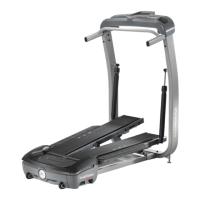
7.Usinga#2Phillipsscrewdriver,removethe2indicated
screws (by ovals) from the Left Crank Cover.
8. Remove the Left Crank Cover from the machine.
9. Place a rag or protective material below the Left Connector
Arm to protect the Shroud from potential scratches from the
Connector Arm.
10. Using a 6mm hex wrench, remove the indicated hardware
(with arrows) that connects the Left Connector Arm and the
Pivot Arm.
Note: The Connector Arm will pivot downward if not lowered
slowly onto the rag protecting the Shroud.
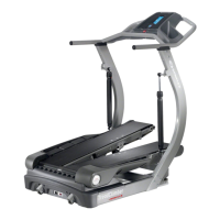
11.Usinga9/16”or14mmsocketandwrench,removethenut
from the Left Crank Assembly.
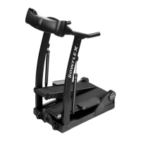
12.AdjusttheCrankPulleruntiltheendoftheBoltisushwith
the Nut (as shown).
Left Crank Assembly
Pivot Arm
Connector Arm
Crank Cover