98
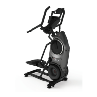
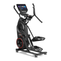
Rear Shroud
Note: Replace any damaged hardware with the new hardware provided
with this kit for re-assembly.
1. Unplug the AC Adapter from the wall outlet and machine.
2. Remove the Right and Left Stabilizer Shrouds from the machine.
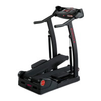
3. Using a 5mm hex wrench, remove the indicated hardware from the
Right and Left Upper Handlebar and place them out of the work area.
Note: Be aware that the Right and Left Upper Handlebar must be sup-
ported when removing the hardware.
4.Usinga#2Phillipsscrewdriver,removetheindicatedscrewfromthe
Rear Shroud.
5. Carefully remove the Rear Shroud from the machine. Place a standard
screwdriver behind and near the middle of the Rear Shroud and gently pry
until it releases. Then move the screwdriver to the bottom and gently pry
until the Rear Shroud comes off.
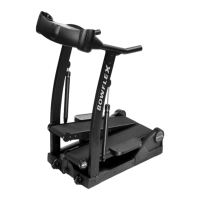
6. Remove the Caps from the machine.
7. Using a 6mm hex wrench, remove the hardware exposed from below
the Cap from both sides of the machine.
8. Slide the Leg Assemblies off of the machine.
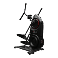
Left Upper
Handlebar
Right Upper
Handlebar
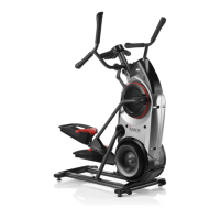
Cap
Leg Assembly
Right Stabilizer
Shroud
Left Stabilizer
Shroud
Cap
Leg Assembly