22
ENGLISH
CONNECTIONS
Function of socket terminal
(see fig. 2)
1 video signal coaxial
(
1
)
2 video signal shield cable
3 video signal coaxial
4 video signal shield cable
(
1
) If the video line ends at this monitor, con-
nect a 75 Ω (violet-green-black-gold) resistor
between terminals 1 and 2.
1 positive video signal twisted
(
2
)
2 negative video signal pair
3 positive video signal twisted
4 negative video signal pair
(
2
) If the video line ends at this monitor, con-
nect the two 56 Ω (green-blue-black-gold)
resistors between terminals 1-5 and 2-5.
5 −
14 ÷ 17.5V supply voltage to monitor
6 +
7 call input from entry panel
8 audio from entry panel
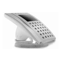
Connector M1
This is used for connecting the unit’s recei-
ver (fig. 1).
Connector CN2
This is used for connecting the unit to the
local telephone line (fig. 1).
NOTE. The unit must be connected on ana-
logue telephone lines only and not digital
ISDN lines.