30 SIMPLY MORE POWER
INSTRUCTION MANUAL BFO H
2
O
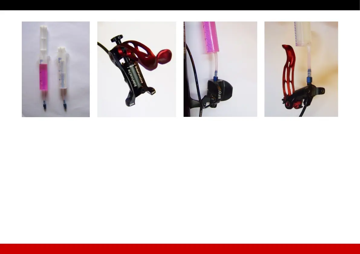
) Push braking uid from syringe (1) into system (pic. 23).
Make sure that no air is pushed into the system.
) Pull lever once or twice up to the stop while pushing.
Braking uid and air bubbles gather inside the syringe (2).
) Tap against syringe slightly.
Air bubbles move upwards.
) Push braking uid from the opposite direction from syringe (2) into
system (pic. 24).
Make sure that no air is pushed into the system.
Braking uid and air bubbles gather inside the syringe (1).
) Tap against syringe slightly.
Air bubbles move upwards.
) Repeat these steps (pic. 23/24) until all the air is pushed out oft he
system.
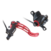
) Remove caliper if necessary. The bleeding connector should be pointing
upwards (pic. 21). This should help, if you are not able to bleed the
brake completely whilst tted (air bubble above bleeding connector).
Trapped air can be removed best in this position.
) Take screw plug (3) out of bleeding port (caliper).
) Screw syringe tting (1) onto ller opening – tighten slightly.
) Remove lever from handlebar.
) Take screw plug (4) out of bleeding port (lever).
) Screw syringe tting (2) onto bleeding port – tighten slightly.
) Fix lever with bleeding port pointing upwards (brake lever at ~45°)
(pic. 22).
Trapped air can be removed best in this position.
Take into consideration that both syringes should be placed vertical
while bleeding. This will ensure that no air will be pressed into the system
accidentally – x if necessary.
Picture 21 Picture 22
Picture 19 Picture 20