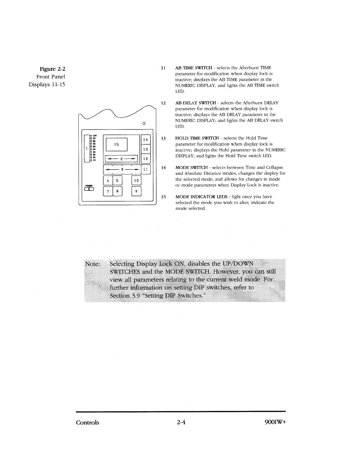
Figure 2-2
Front Panel
Displays 11-15
—
1
loo
vo
ao
70
so
so
40
30
20
10
14
13
1
5
12
-
F
---
2 --..--
POWER
—.---,--,—,—
—
[ 1
3
4
5
10
9
7
8
11
AB TIME SWITCH - selects the Afterburst TIME
parameter for modification when display lock is
inactive; displays the AB TIME parameter in the
NUMERIC
DISPLAY;
and lights the AB TIME switch
LED.
12
AB DELAY SWITCH - selects the Afterburst DELAY
parameter for modification when display lock is
inactive; displays the AB DELAY parameter in the
NUMERIC
DISPLAY;
and lights the AB DELAY switch
LED.
13
HOLD TIME SWITCH - selects the Hold Time
parameter for modification when display lock is
inactive; displays the Hold parameter in the NUMERIC
DISPLAY; and lights the Hold Time switch LED.
14
MODE SWITCH - selects between Time and Collapse
and Absolute Distance modes; changes the display for
the selected mode; and allows for changes in mode
or mode parameters when Display Lock is inactive.
15
MODE INDICATOR LEDS - light once you have
selected the mode you wish to alter; indicate the
mode selected.
Note: Selecting Display Lock ON, disables the IJP/DOWN
.
SWITCHES and the MODE SWITCH. However, you can still
view all parameters relating to the current weld mode. For
further information on setting DIP s\Viteh.es, refer to
Section 3.9 "Setting DIP Switches."
Controls
2-4
900IW+