Electrical Connections
6-1
Digital Compact
2002 BRANSON Ultrasonics Digital Compact Version 22.08.2002
6 Electrical Connections
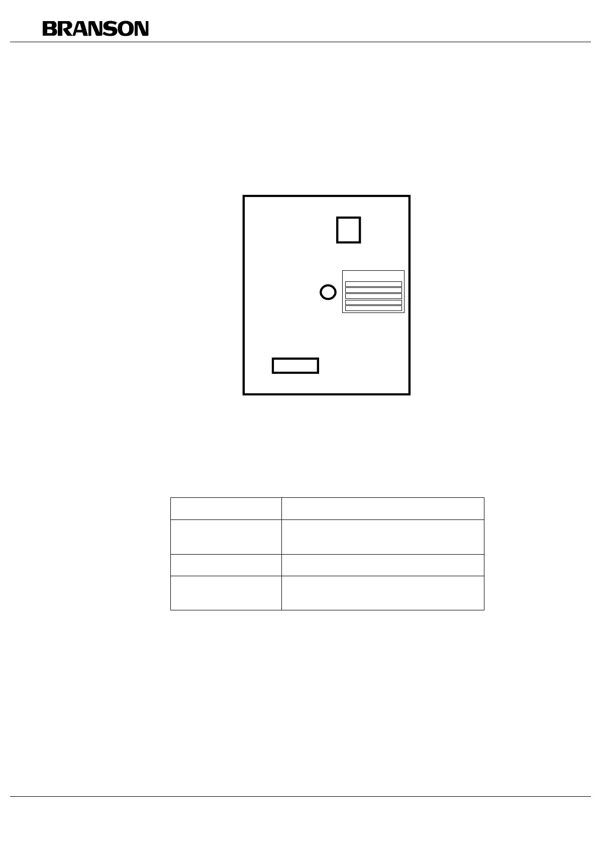
Fig. 6-1 Electrical connectors at the rear of the power supply
Tab. 6-1 Connectors at the rear of the DC power supply module
Connector Function
J1 Mains supply
connector
Connection to mains supply
J2 RF connector Converter connector
J3 Control/ alarm
connector
For information on pin assignment,
please refer to Tab. 6-3.
CE
Model
Powe r
Input
Serial No.
Year of Manufacture
UPS 480
800 W
200-245 V, 5 A, 50/60 Hz
J3
J2
J1