11
Series 71 – Modulating Controller - Electric Actuator
Installation, Operation and Maintenance Manual
Fault Status
The Fault LED located at the bottom left will turn on during a fault
condition The occurrence of a fault indicates that user intervention is
required to restore operation and these indicators attempt to provide the
diagnostic information needed to accomplish this
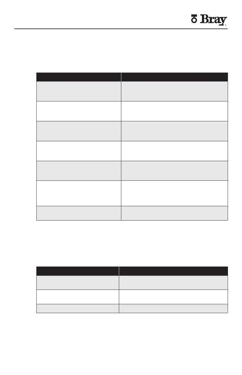
Fault LED (flashing) Other LED Fault Condition
-mA Input LED flashing Command Signal Fault Input signal is
-mA mode and the input signal is less
than mA or greater than mA
-V Input LED flashing Command Signal Fault Input signal
is -V mode and the input signal is
greater than V
-V Input LED flashing Command Signal Fault Input signal is
-V mode and the input signal is greater
than V
-V Input LED flashing Command Signal Fault Input signal is
-V mode and the input signal is less
than V or greater than V
Output LED flashing
(selected output mode)
Feedback Potentiometer Fault
potentiometer voltage is outside of the
V-V range when near limits
Calibration LED Calibration Fault Calibration failed due
to Feedback Potentiometer Fault or the
motor was not able to reach end of travel
in expected time
Open LED & Close LED
both flashing
Limit Switch Fault Both limit switches
activated at the same time
Figure – Fault Indication LED Status Description
Refer to the Troubleshooting section for the actions required to clear a fault
Calibration
The calibration (CAL STATUS) LED indicator located at the bottom right
serves as a calibration status indicator for the S Servo
Calibration (CAL STATUS) LED Description
OFF Autocalibration routine previously
completed successfully
ON (slowly flashing) S Servo operating using default factory
calibration settings
ON (quickly flashing) Calibration routine in progress
Figure – Calibration Status LED Status Description
 Loading...