13
Series 71 – Modulating Controller - Electric Actuator
Installation, Operation and Maintenance Manual
6.0 HARDWARE DESCRIPTION
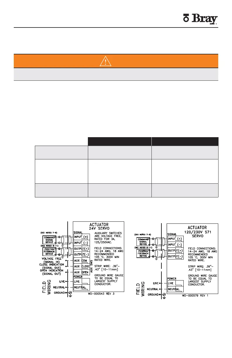
Terminal Connections
WARNING
Turn off all power and lockouttag out service panel before installing or modifying any
electrical wiring
There are two categories of connections voltage level and connection type
Field terminals are provided on the unit for the landing of stripped wires
connecting the S Servo to the field wiring needed for it successfully
operate All field terminals are positioned on the left side of the controller
easily accessible facing the conduit entries Internal actuator connections
are made at the factory and should not require any customer adjustment
Auxiliary switches are provided voltage free and rated for operation up to
A at VAC
Field Terminals Internal Connections
High voltage ( V) Power (Live Neutral) Motor Terminals
Heater Header
Low voltage ( V) Input Signal
(Input Input-)
Output Signal
(Output Output-)
FB Pot Header
Limit Switch Header
Voltage Free Auxiliary Switch
(Com Close Open)
Auxiliary Switch Header
Figure Terminal Connection Categories
A Division of BRAY INTERNATIONAL, Inc.
A Division of BRAY INTERNATIONAL, Inc.
·
·
·
·
·
·
·
·
·
·
·
·
·
·
Figure S Servo Field Wiring


 To Next Page