7
Series 71 – Modulating Controller - Electric Actuator
Installation, Operation and Maintenance Manual
Configurable Settings
Settings can be changed locally by utilizing the push-button associated with
each product setting Each push-button is labeled and placed below a set
of LEDs with individual labels corresponding to the setting Settings are
changed using the push-button The next LED in the sequence will illuminate
once the push-button is pressed
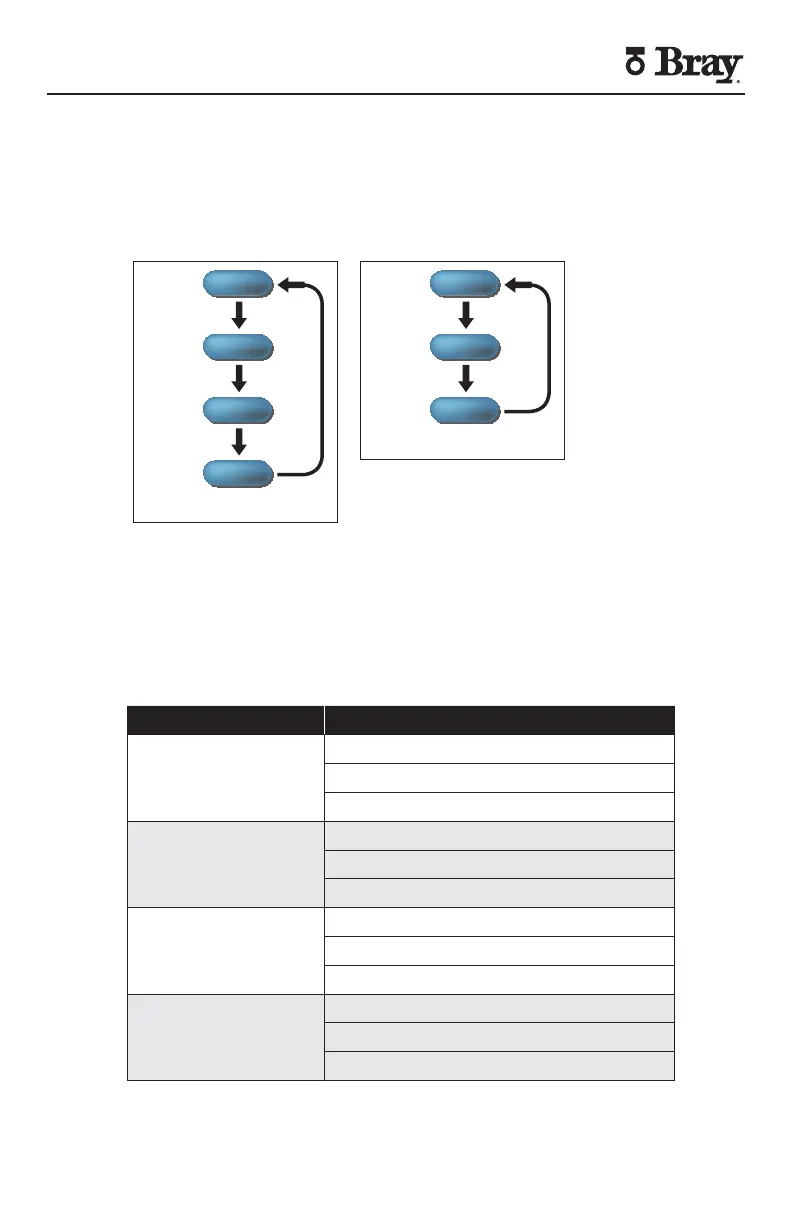
4-20mA
0-10V
0-5V
INPUT SIGNAL
4-20mA
0-10V
0-5V
OUTPUT SIGNAL
2-10V
Figure Servo Push Button Menu Flow
Description of Settings
Input Signal Type - Configurable
Input signals position the valve under control based on the magnitude of
the signal The minimum value corresponds to the closed position and the
maximum value to the open position Only one input signal can be active at
a time
Input Setting Description
-mA (default)
Analog Current Range
Minimum mA
Maximum mA
-V
Analog Voltage Range
Minimum V
Maximum V
-V
Analog Voltage Range
Minimum V
Maximum V
-V
Analog Voltage Range
Minimum V
Maximum V
Figure Servo Input Settings