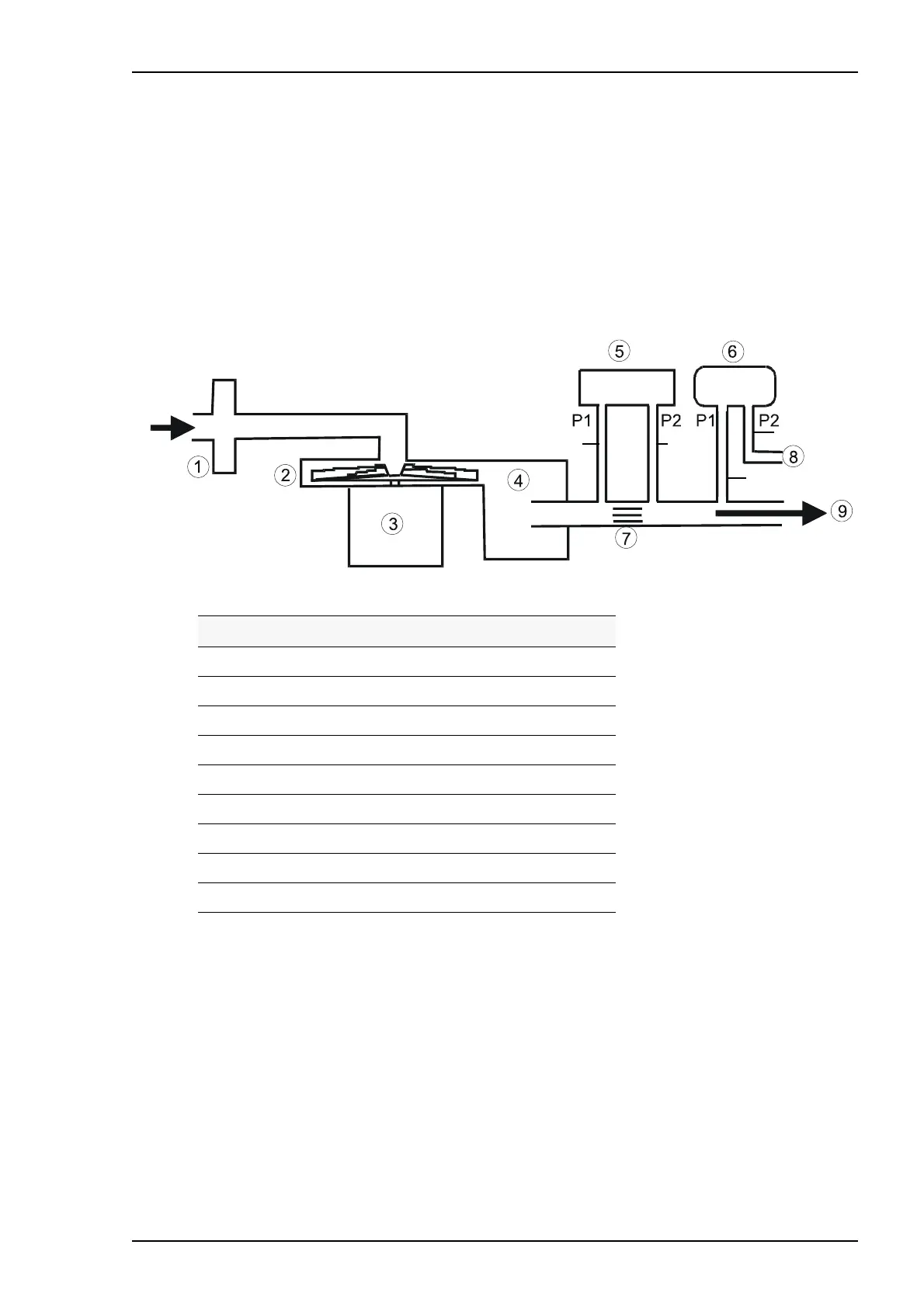
PV 101+/PV 102+ Service Manual FUNCTIONAL DIAGRAMS
Doc. No. 003259 En Issue: X-1 BREAS MEDICAL 6–1
6 FUNCTIONAL DIAGRAMS
This chapter contains a diagram of the pneumatic system of the ventilator and a block
diagram of the PV 101+/PV 102+’s functions.
6.1 Pneumatic diagram
The pneumatic diagram shows the pneumatic components of the air circulation system
of the PV 101+/PV 102+.
No. Description
1 Patient air inlet (through air filter)
2 Blower
3 Motor
4 Silencer
5 Flow sensor (2)
6 Pressure sensor (1)
7 Honeycomb material
8 Reference pressure tube
9 Patient air tube
Sensor 1
Sensor 2
Red
Green
Black
Blue