16
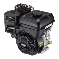
6. 10R200 and 10U200 engines: Disconnect black wire
(I) from stop switch located at rear of blower housing.
Mark each end of wire for reassembly.
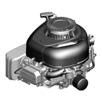
17
106200 engine: Mark each wire on stop switch for
reassembly and then disconnect wires from stop switch.
A. Top Terminal (H) - Red ground wire
B. Center Terminal (J) - Black coil wire
C. Bottom Terminal (K) - Black low oil sensor wire, if
equipped
7. Carefully remove blower housing from engine and set
aside.
8. Turn flywheel so that magnet is away from armature
legs (L).
18
9. Loosen two screws (M and N).
10. Slide Armature (P) away from flywheel.
11. Tighten screw (N) to secure Armature.
12. Turn flywheel so that magnet is aligned with armature
legs (Q).
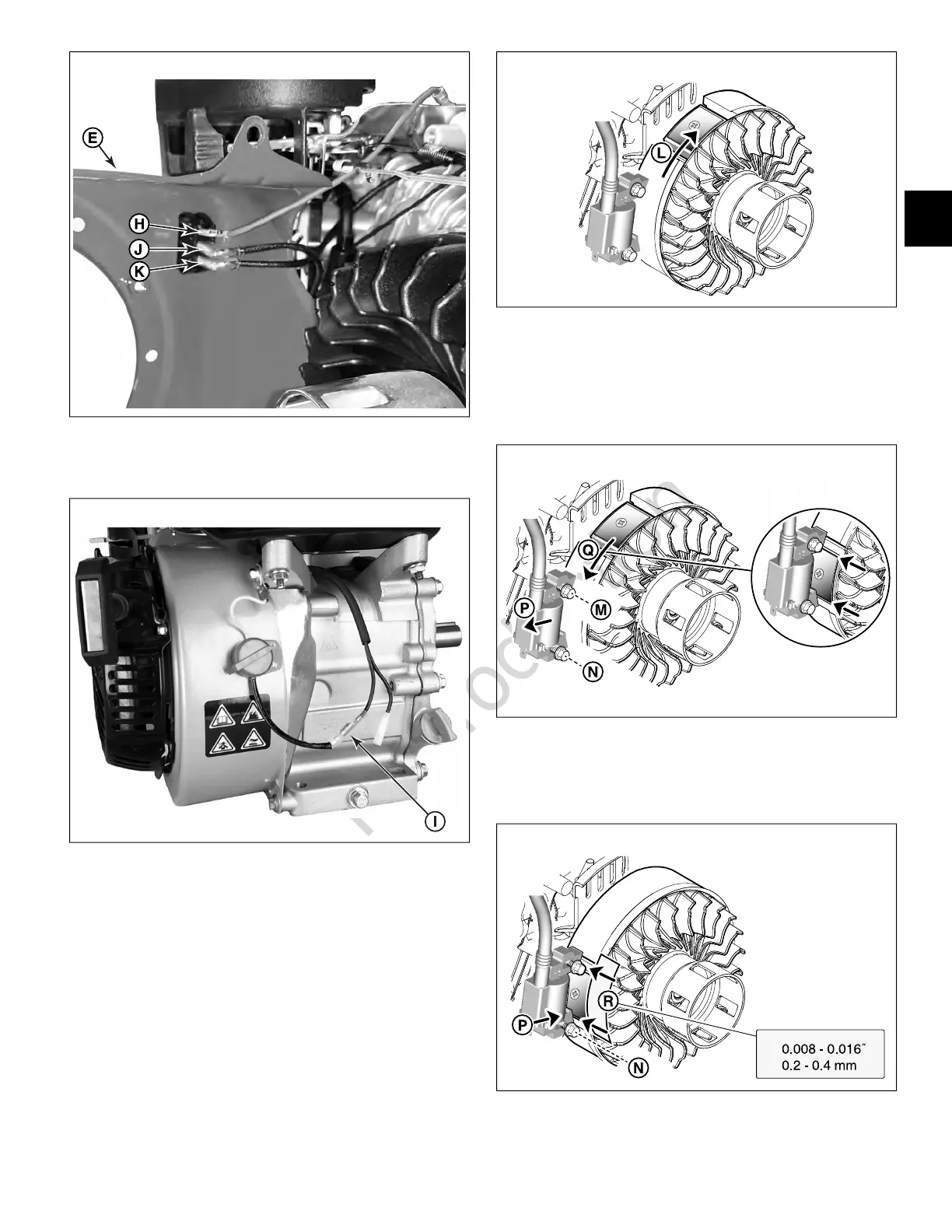
19
13. Insert a gauge 0.008 - 0.016 in. (0.2 - 0.4 mm) thick (R)
between flywheel and armature legs.
14. Loosen screw (N). Press armature legs (P) tight against
flywheel.
20
15. Torque both screws (M and N) to the value listed in
Section 13 - Engine Specifications
.
21
2
 Loading...