49
2. If head passes visual inspection, check valve guides
for wear. If valve guides meet or exceed the reject
dimension shown in
Section 13 - Engine
Specifications
, replace the cylinder head.
3. Inspect valves for wear or damage. If slight wear is
found, lap the valve and seat as instructed in the
following steps. If excessive wear or damage is found,
replace cylinder head.
Note:
Valve faces can be resurfaced on a commercially
available valve grinder. However, Briggs & Stratton does
not recommend this practice because the quality of the
resurfacing may be insufficient.
4. Place a small amount of lapping compound #94150
around the valve face of one valve. Make sure that
lapping compound only comes into contact with the
valve face and valve seat.
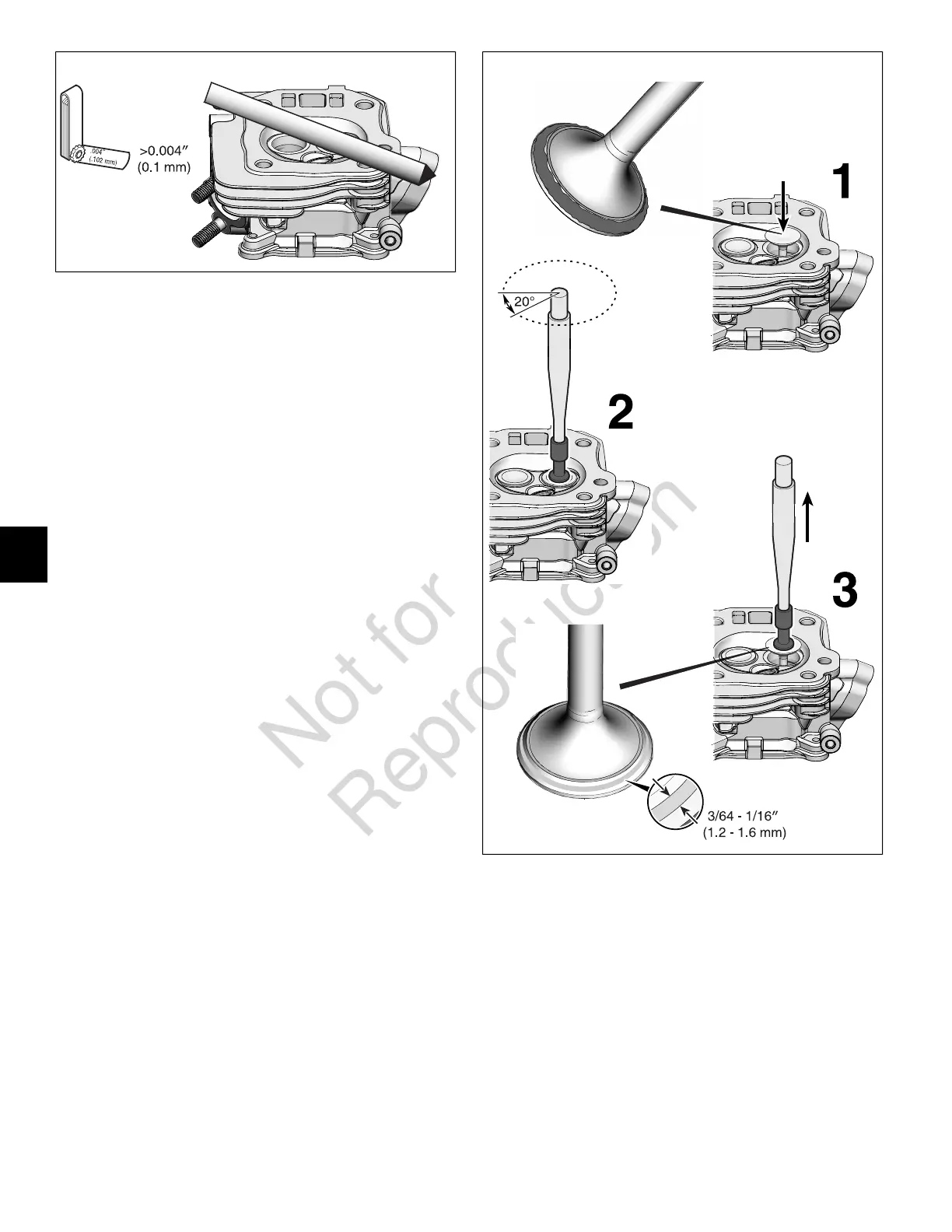
5. Oil the valve guide and valve stem and then insert the
valve into the cylinder head.
6. Using Valve Lapping Tool #19258, rotate the valve
clockwise and counterclockwise, approximately 20 °
each way. Continue this action for a short period of
time.
7. Remove the valve. Use a rag dipped in mineral spirits
to clean the valve face. Inspect the surface made by
the lapping compound. Make sure that the width of the
lapped surface is equal around the entire valve and
within 3/64 - 1/16" (1.2 - 1.6 mm). If both conditions are
not met, replace the valve.
8. Repeat this procedure for the remaining valve.
50
9. Use a rag dipped in mineral spirits to thoroughly clean
all lapping compound from the valves and cylinder head.
Assemble Cylinder Head
1. Install push rod guide plate (W) into cylinder head (G)
and secure with rocker arm studs (U). Torque rocker
arm studs to value listed in
Section 13 - Engine
Specifications
.
2. Lightly coat valve stems with lubricant, then insert
valves (Q) into cylinder head (G).
Note:
Do Not get lubricant on valve face, valve seat, or
exposed end of valve stem.
56 BRIGGSandSTRATTON.COM
7
 Loading...