7
Revision 1.1
09/2024
B1051UL
INSTALLATION INSTRUCTIONS - WIRING 2
INSTALLATION INSTRUCTIONS - WIRING 2
A
RAIL
COMMON
ISOLATED
COMMON
B
RAIL
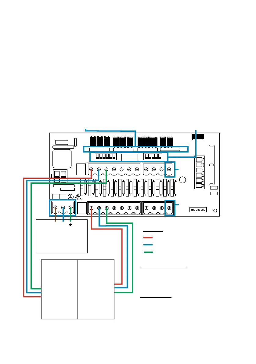
Separate connections
are provided on input 2
for Hot & Cold wash
signals
Seperate connections
are provided on input 2
for Hot & Cold wash
signals.
.
AFS
AFS
COMMON
ISOLATED
ISOLATED
L N
L
N
RP1, RP2, RP3 & RP4
Remove to allow signal below 90 volts AC or DC (min
12V)
S1 & S2
Switch to common signals on the
B-rail
In some cases, the interface board or solenoids in the host machine are not common. For example:
The softener solenoid on some machines is not linked via a common wire to the other solenoids.
If this is the case, the signal must be isolated from the common B rail on the Board. This is done by
Switching the appropriate switch (S1 & S2 to isolated, ie. Downward position). If in doubt switch the
appropriate switch for each incoming signal source.
FAILURE TO SWITCH THE APPROPRIATE SWITCH WOULD RESULT IN UNIT FAILURE.
DO NOT ATTEMPT TO SWITCH THE SWITCHES WHEN THE POWER IS ON.
Power Supply
100-240v(AC) 50/60Hz
Sourced from a point which
is isolated when the host
machine is o
B Rail
(Negative)
With the switches in
an upright position,
an isolated (neutral/
negative) input
signal can be taken
to the B Rail
A Rail
(Positive)
The positive (live)
signal from each
input must be taken
to the relevant
connection on the
A Rail.
INPUT 1 - Pre-Wash
INPUT 2
- Main Wash
INPUT 3
- Rinse
Example
Recommended Wiring
Max Size = 1.5mm²
Min Size = 0.5mm²
Current = 0.5A
Safety Warning
If low voltage signals are used, signal wires to
the A and B rails should be routed in separate
cable from the main power to the unit.
Suitable grade wire must be used.
Signal Inputs 90v-240v AC or DC