Model 871A User’s Manual LASER INPUT
Bristol Instruments, Inc. 12
If the laser under test has a free space beam, it must be launched into a fiber-optic
patchcord for entry into the 871 Laser Wavelength Meter. The BC-1 Fiber-Optic Input
Coupler offered by Bristol Instruments is a convenient method of doing this.
(1) Install the BC-1 coupler in any two-axis (Θ-Φ) adjustable optical mount that can
accommodate a 1 inch (25.4 mm) diameter optic. Optical mounts with X–Y
translational adjustment may be convenient in some laboratory configurations.
(2) Center the laser beam on the 2.5 mm input aperture of the BC-1 coupler. Using the
angular adjustments of the optical mount, adjust the face of the beam coupler to be
orthogonal to the laser beam.
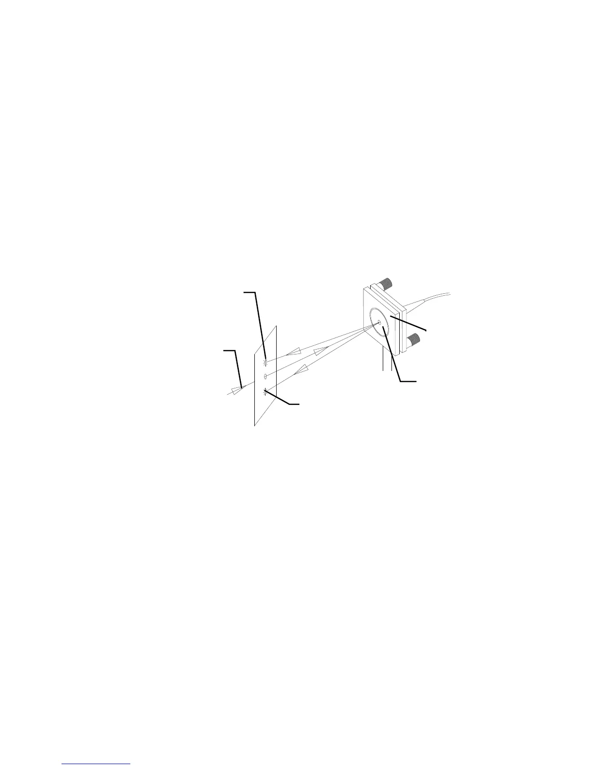
(3) Two back reflections from the BC-1 coupler should be visible near the laser’s output
aperture. They can also be seen by placing a white card (with a hole in the center) in
the beam path as shown in Figure 3.3. Adjust the optical mount until the reflections
symmetrically straddle the input beam.
Figure 3.3: Aligning the BC-1 Fiber-Optic Input Coupler
(4) Maximize throughput, using visual or power meter detection, by making minor
angular adjustments with the Θ-Φ optical mount.