Model 871A User’s Manual LASER INPUT
Bristol Instruments, Inc. 11
1 Ensure that all fiber-optic connectors are clean and dry. The 871 system is shipped
with a fiber cleaning kit consisting of a package of connector cleaning sticks, clean
wipes, and fiber-optic splice & connector cleaner spray. See Appendix F for cleaning
instructions.
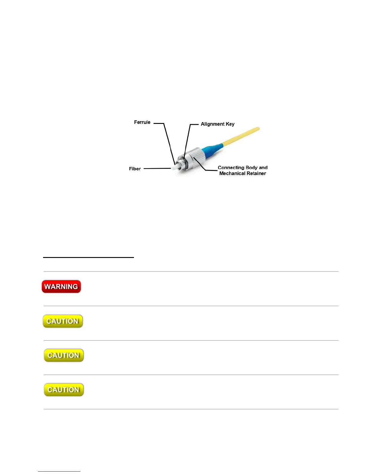
2 Connect your fiber-optic patchcord to the pre-aligned FC/PC fiber-optic connector on
the instrument’s front panel. Make certain that the alignment key on the fiber-optic
patchcord’s connector (Figure 3.2) is properly seated in the slot of the input
connector.
Figure 3.2: Basic Components of an FC/PC Fiber-Optic Connector
3 Tighten the mechanical retainer with a light to medium finger-tightness. Exceeding
this torque may result in a poor connection or may damage the connector.
Free-Beam Laser Input
Never inspect or clean a fiber-optic cable without first disconnecting the entire
cable assembly from the optical source. Failure to take this precaution can
permanently damage your eyesight.
Use care in handling fiber-optic connectors. Always clean the fiber end prior to insertion
into the instrument’s fiber-optic connector for optimum performance. Failure to do so can
result in damage to the instrument.
Maximum safe input for the 871 Series Laser Wavelength Meter is 10 mW of CW or time-
averaged optical power, or 0.5 mJ of pulsed laser energy (10 ns pulse). Laser input
power in excess of these values can result in damage to the instrument.
Maximum safe input for the BC-1 Series is limited by the fiber-optic patch cord connected
to the BC-1. Refer to the maximum optical power and laser energy specifications
provided by the fiber-optic patch cord manufacturer.