Model 871A User’s Manual INITIAL INSTRUMENT SETUP
Bristol Instruments, Inc. 8
1 Verify that the line power meets the requirements shown below.
• 95 to 260 VAC
• 47 to 63 Hz
• Protective Ground
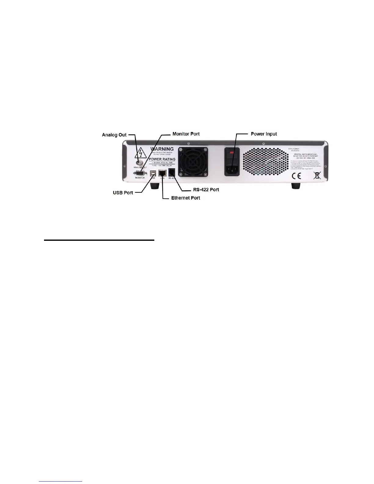
2 Connect the line-power cord to the power input connector on the instrument’s back
panel (Figure 2.1).
3 Connect the other end of the line-power cord to the power receptacle.
Figure 2.1: Back Panel
Signal Output Connections
The 871 Laser Wavelength Meter has the following connections for signal output and
communications. These connections are located on the instrument’s back panel
(Figure 2.1).
• USB Port - Interface to a PC for instrument control and data reporting.
• Ethernet Port – Interface to a PC for instrument control and data reporting.
• RS-422 – Interface to a PC for real-time data reporting.
• DB-9 Monitor Port - Used to trigger measurements and view measurement
timing. A full description of the external trigger and the measurement timing is
provided in Chapter 5.
• Analog Out – Used to supply voltage for stabilizing a laser source. A full
description of the Analog Out and the PID Control function is described in
Chapter 4.
1 Connect the USB interface cable to the USB port on the back panel of the instrument.
2 Connect the other end of the USB cable to a USB port on your PC.