Model 871A User’s Manual USING THE LASER WAVELENGTH METER
Bristol Instruments, Inc. 17
PID Controller Screen
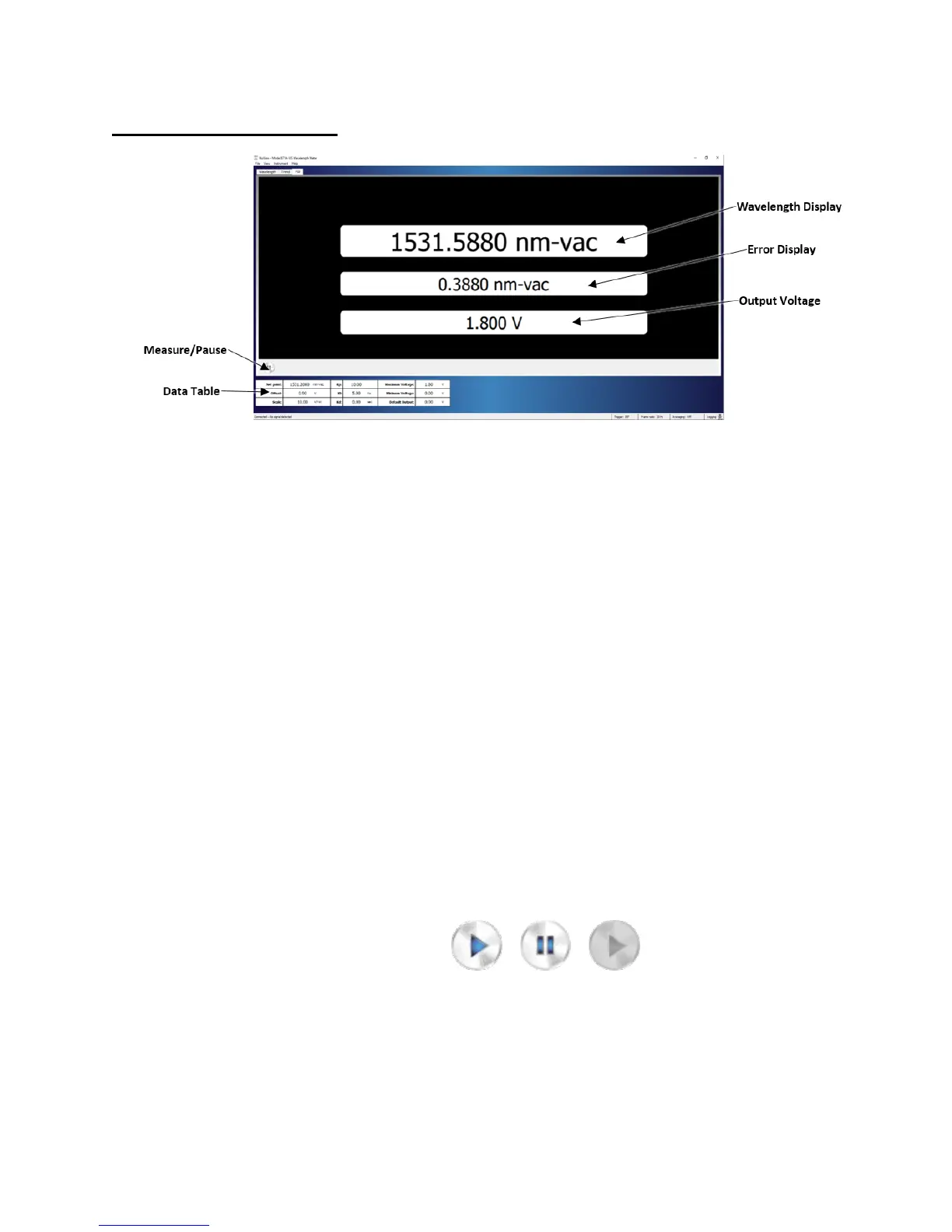
Figure 4.5: PID Controller Screen
The PID Controller Screen displays the settings for the 871-system’s internal PID
controller and reports the most recent wavelength reading and output voltage supplied
through the Analog Out BNC connector on the back panel of the wavelength meter
(Figure 2.1).
The calculation behind the PID Controller Screen consists of three separate voltage
parameters input by the user. The first parameter, K
p
, accounts for the current
(Proportional) error magnitude and has the highest contribution to guiding the measured
wavelength towards the set point. The second parameter, K
i
, accounts for the sum of
past errors (Integral) to minimize the effects of outlying data peaks or spikes on the
correction voltage. The third parameter, K
d
, factors in the current rate of change
(Derivative) to avoid oscillation about the desired wavelength. These three components
ensure swift correction of the laser to the desired frequency with minimal overshooting or
oscillation.
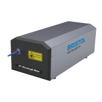
Measure/Pause
Enables the PID calculations to determine the output voltage. Selecting the
Measure button (left) initiates the PID calculation. After the Measure button is
selected, it changes its appearance to the Pause button (middle). The PID
calculation updates continuously until the Pause button is selected. Selecting the
Pause button stops data collection. When the instrument is not connected, the
Measure button changes its appearance to its greyed-out inactive state (right).