Model 871A User’s Manual MAKING MEASUREMENTS
Bristol Instruments, Inc. 33
Monitor Port
The Monitor Port on the rear panel of the 871 Laser Wavelength Meter provides the input
for a control trigger and monitoring of the data processing and output. The Monitor Port
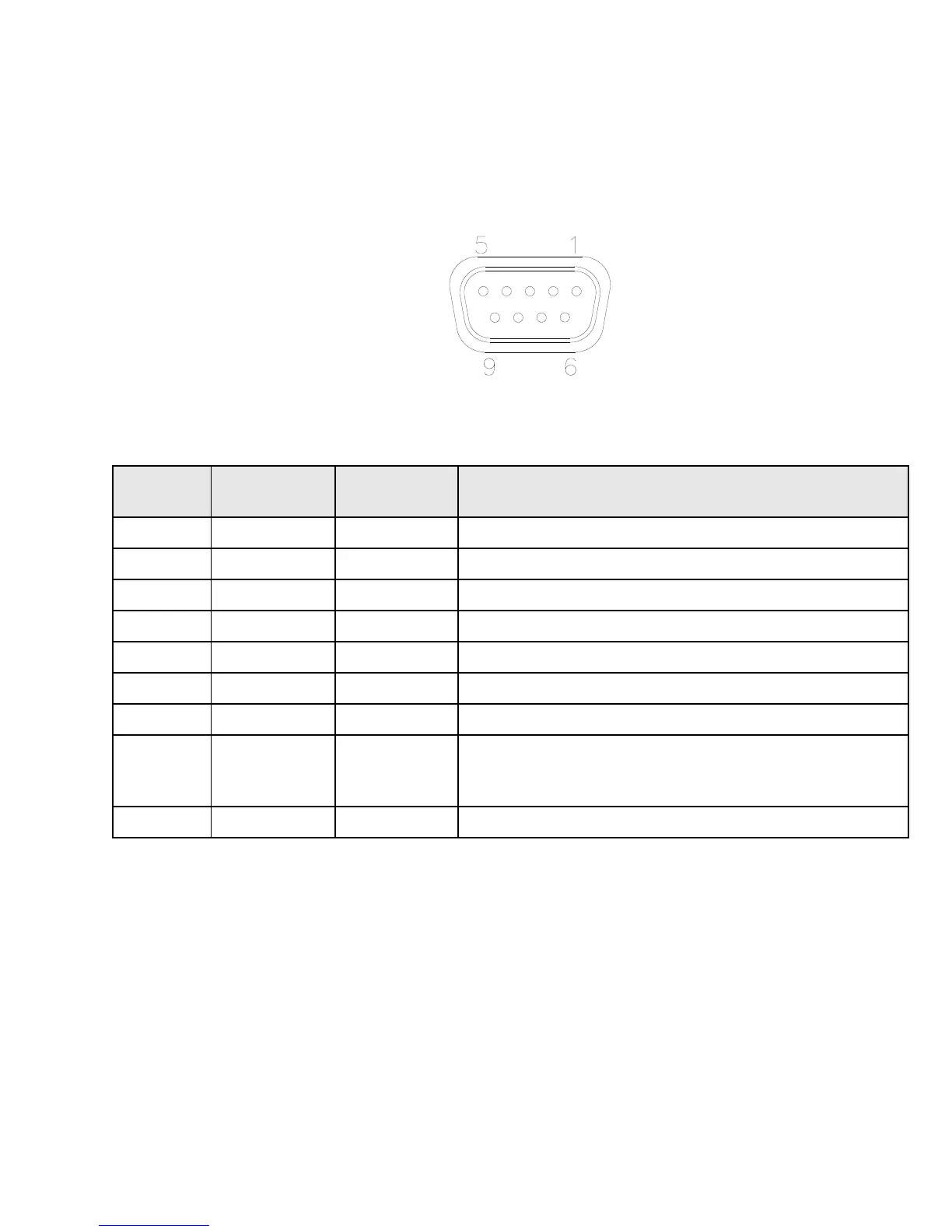
uses a 9-pin, female, D-sub style connector shown in Figure 5.2 and with a pinout
described in the table below.
Figure 5.2: Monitor Port
Monitor signal which is set high during the processing of
collected data. At the completion of data processing, results
are sent out the RS-422 port.