Brivo ACS Installation Manual ACS5000-E
ENG-WI-001 © 2005 Brivo Systems, LLC. All rights reserved. Page 13
a) Install the tamper switch in each chassis by removing the hex collar, seating the
switch inside the provided mounting bracket, and reattaching and tightening the
hex collar.
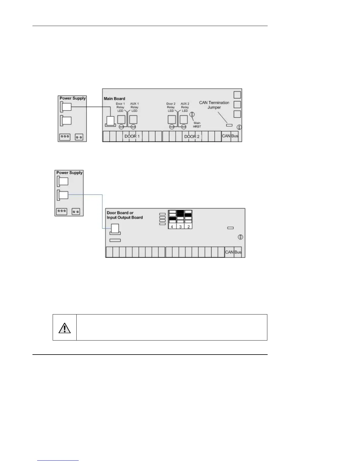
Connect the MAIN BOARD and all expansion boards to a power supply
board
1. Connect the MAIN BOARD in the control chassis to the power supply board.
Figure 1. Connect MAIN BOARD to Power Supply
2. If there is a DOOR BOARD or an INPUT OUTPUT BOARD in the control chassis,
connect that to the power supply board.
Figure 2. Connect Expansion Board to Power Supply
3. If there are expansion chassis, connect each DOOR BOARD and INPUT OUTPUT
BOARD to the power supply board in each chassis.
a) Use the power cable that came with each circuit board kit.
b) The Power connector uses a PC-style 4-wire molded (Molex) connector to deliver
+12V, Ground, AC, Power Detection, and Earth Ground to each board from the
power supply.
WARNING: Power Supply
DO NOT USE ANY POWER SUPPLY OTHER THAN THOSE SUPPLIED WITH
YOUR BRIVO PRODUCT.