Brivo ACS Installation Manual ACS5000-E
ENG-WI-001 © 2005 Brivo Systems, LLC. All rights reserved. Page 27
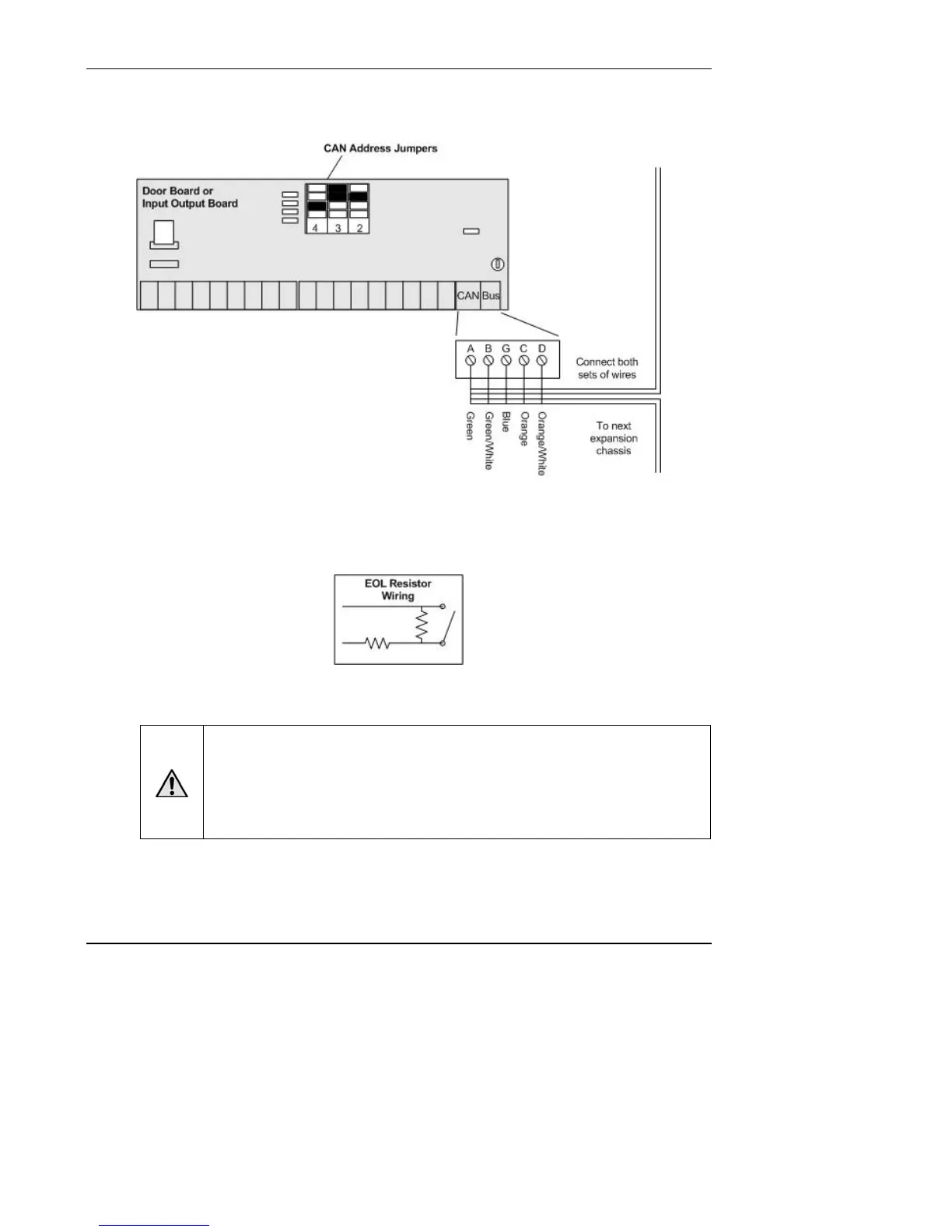
Wire INPUT OUTPUT BOARDs
Figure 16. Wire INPUT OUTPUT BOARD
1. An INPUT OUTPUT BOARD has 8 output relays with 125VAC, 3A Relays, and 8 inputs.
The
inputs can be wired for line supervision.
Figure 17. EOL Resister Wiring
WARNING: Powering Electronic Strikes and Latches
DO NOT POWER ELECTRONIC STRIKES AND LATCHES WITH THE BATTERY
(OR OTHER POWER SOURCE) USED TO POWER THE CONTROL PANEL;
DOING SO WILL CAUSE DAMAGE TO THE BRIVO CONTROL PANEL. USE ONLY
A UL LISTED BURGLAR ALARM OR ACCESS CONTROL SYSTEM TO POWER
ELECTRONIC STRIKES AND LATCHES.
Ground the control chassis.
1. Wire the control chassis to the green Earth Ground screw.