Brivo ACS Installation Manual ACS5000-E
ENG-WI-001 © 2005 Brivo Systems, LLC. All rights reserved. Page 14
WARNING: Powering Electronic Strikes and Latches
DO NOT POWER ELECTRONIC STRIKES AND LATCHES WITH THE BATTERY
(OR OTHER POWER SOURCE) USED TO POWER THE CONTROL PANEL;
DOING SO WILL CAUSE DAMAGE TO THE BRIVO CONTROL PANEL. USE ONLY
A UL LISTED BURGLAR ALARM OR ACCESS CONTROL SYSTEM TO POWER
ELECTRONIC STRIKES AND LATCHES.
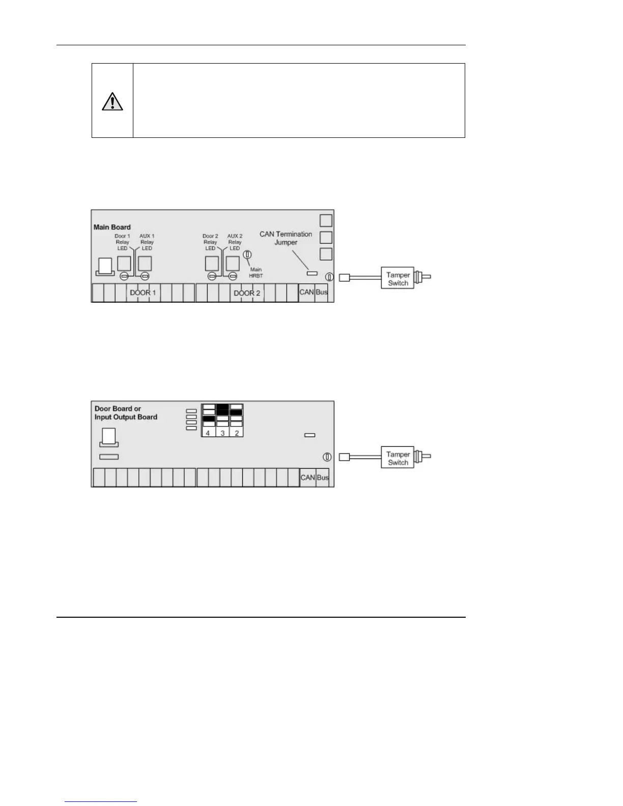
Connect the tamper switch to the MAIN BOARD and to one board in each
expansion chassis.
1. Connect the tamper switch to the MAIN BOARD in the control chassis.
Figure 3. Connect Tamper Switch to MAIN BOARD
a) The tamper header connects to the supplied tamper switch.
b) The header connector for the tamper switch should be connected to the
TAMPER pins located on the lower right side of the MAIN BOARD and each
expansion board.
2. Connect the tamper switch to one expansion board (DOOR BOARD or INPUT OUTPUT
BOARD) in each expansion chassis.
Figure 4. Connect Tamper Switch to Expansion Board
NOTE: If a chassis has two boards, connect the tamper switch to the upper board.
NOTE: If the tamper switch is not going to be used, leave the supplied jumper on this
connector to keep the circuit closed.