Brocade FastIron GS and FastIron GS-STK Hardware Installation Guide 43
53-1001783-01
Upgrading hardware
3
DRAFT: BROCADE CONFIDENTIAL
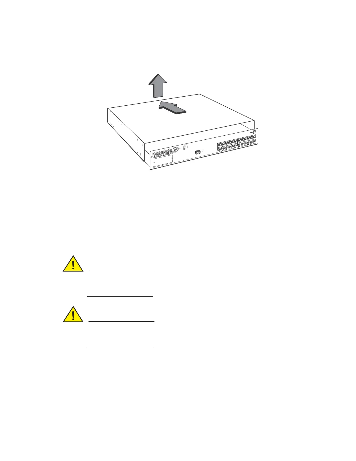
FIGURE 36 Removing the cover from an FGS device.
Installing the EEPROM
1. Remove the EEPROM from the package and align the lead pins over the EEPROM socket. Refer
to Figure 37 on page 43 for the EEPROM socket location on FGS devices. The semicircular
indentation on the EEPROM is located on the same end as pin 1.
.
2. Align the semicircular indentation on the EEPROM with the semicircular cut-out on the
EEPROM socket and gently push the EEPROM into the appropriate socket (for FGS 624 and
648 devices the socket number is U37.
Make sure you insert the EEPROM so that lead pin 1 goes into the correct hole as shown in the
appropriate illustrations. If you accidentally insert the EEPROM backwards, the device will not
work and may be damaged when you power it on.
Do not push too hard. If the EEPROM does not readily go into the socket, stop pushing and verify
that the lead pins are straight and aligned over the holes. Straighten any crooked pins, then try
again.
FIGURE 37 EEPROM socket and memory DIMM locations on FGS 624 and 648 devices
 Loading...