2-10
The ignition switch is key-operated and has OFF, RUN and START positions. The ignition
switch should always be turned off and the key removed when the vehicle is left unattended.
The BMC RT-400 is equipped with a standard lighting package. The controls for the lights
are located in
the 15-button panel located below the main display scre
en. Stop lights are
controlled by operating the foot brakes. The turn signal control is also located on the 15-
button panel located below the main display screen. The emergency flasher lights are
actuated by engaging the left and right turn signal buttons simultaneously. Repeating this
will disengage the emergency flasher lights.
The steering column provides tilting and telescope features and each have a hold lever on
the side of the column to hold the column in the preferred position for the Operator.
The park brake switch is located on the 12-button panel located to the right of the operator.
To apply, ensure that the machine is stopped and push the N/P (Neutral/Park) side of the
rocker switch and the switch itself will light up. Once the N/P button has been engaged, the
gear display on the main display will show N and the parking brake light will illuminate below
the neutral indicator. The foot brake and accelerator pedals are located and operated as
they are in other vehicles already familiar to the operator.
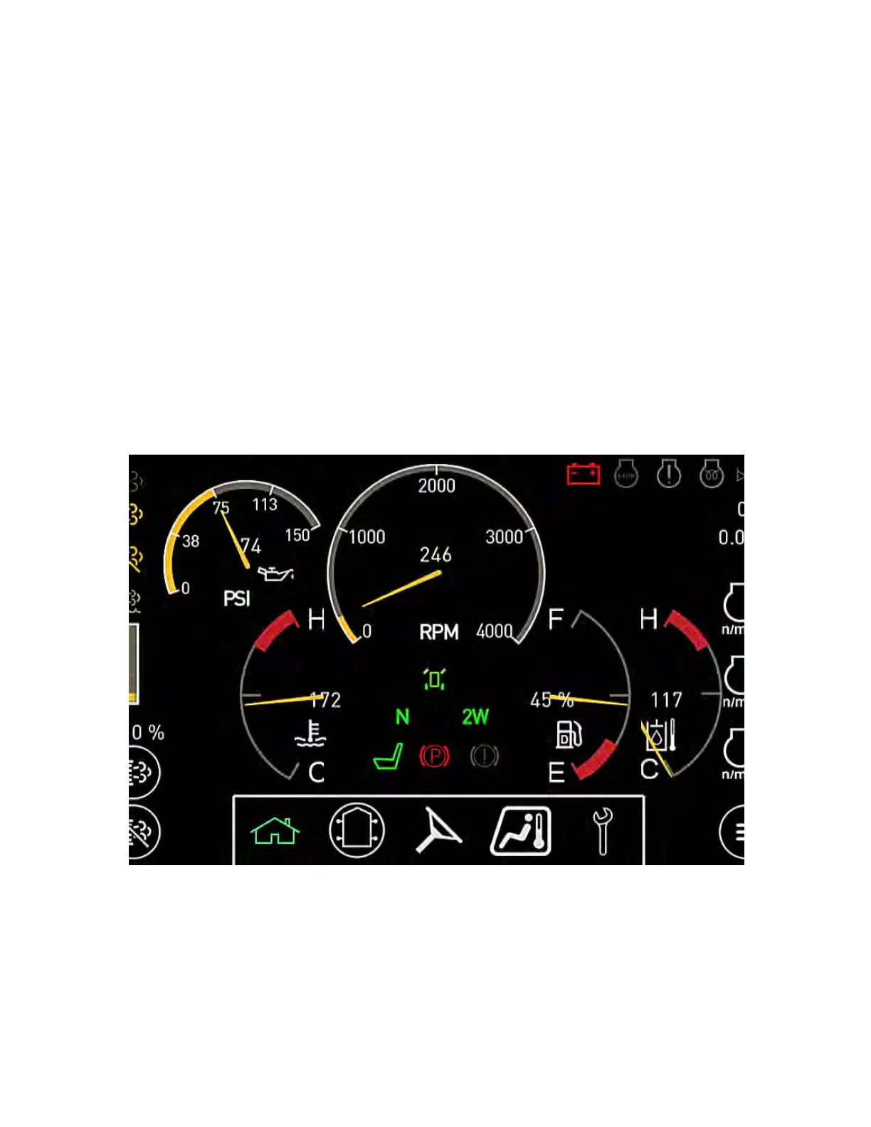
Example of Home Page