1-8
Brooks
®
Digital MFC's & MFM's
Section 1 Introduction
Installation and Operation Manual
X-TMF-SLA5800-Series-RevB-MFC-eng
Part Number: 541B187AAG
January, 2017
RS485 Communications
The Brooks Digital Series is equipped with RS485 communication
capability. Refer to Figure 1-4 (Analog I/O pin connections), that enables
the device to communicate via a personal computer for process control.
Baud rate selections for the Brooks Digital Series related to RS485 are:
1200, 2400, 4800, 9600, 19200 and 38400 baud and can be selected via
the Brooks Expert Support Tool (BEST) .
The RS485 is essentially a multidrop connection. It allows a maximum of
32 devices to be connected to a computer system. Personal computers are
not equipped with RS485 ports as standard. An RS232/USB to RS485
converter or RS485 interface board is therefore required to connect an
RS485 network to a standard personal computer. The RS485 bus, a daisy
chain network, meaning that the wires are connected at the units as in Figure 1-1.
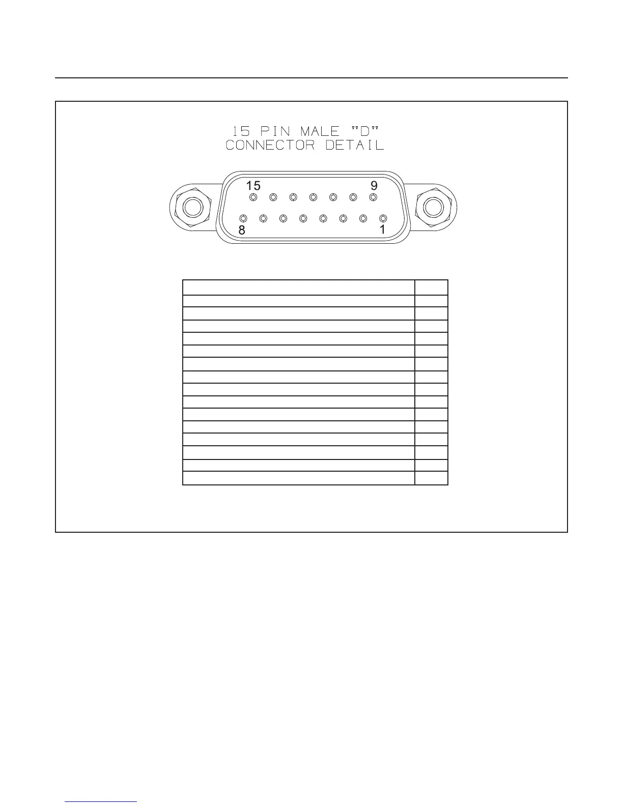
Figure 1-4 SLA5800 Series RS485 15-Pin Analog Connector and Pinouts
Function PIN
Setpoint: Common Input (-) 1
Flow Signal: 0(1) -5 Vdc, 0-10 Vdc (Option), Output (+) 2
TTL Alarm: Open collector, Output (+) 3
Flow Signal: 0(4)-20 mA, Output (+) 4
Power Supply: +13.5 Vdc to +27 Vdc(+) 5
Not Connected 6
Setpoint: 0(4)-20 mA, Input (+) 7
Setpoint: 0(1)-5 Vdc, 0-10 Vdc, Input (+) 8
Power Supply: Common (-) 9
Flow Signal: Common, Output, (-) 10
Not Connected 11
Valve Override: Input 12
Auxilliary: RT Input, 0-5 Vdc, 0-10 Vdc, Input (+) 13
RS-485: Common B (-) 14
RS-485: Common A (+) 15
Note: Aux Input is used for Remote
Transducer Pressure Controllers only.