1-3
Section 1 Introduction
Brooks
®
Digital MFC's & MFM's
Installation and Operation Manual
X-TMF-SLA5800-Series-RevB-MFC-eng
Part Number: 541B187AAG
January, 2017
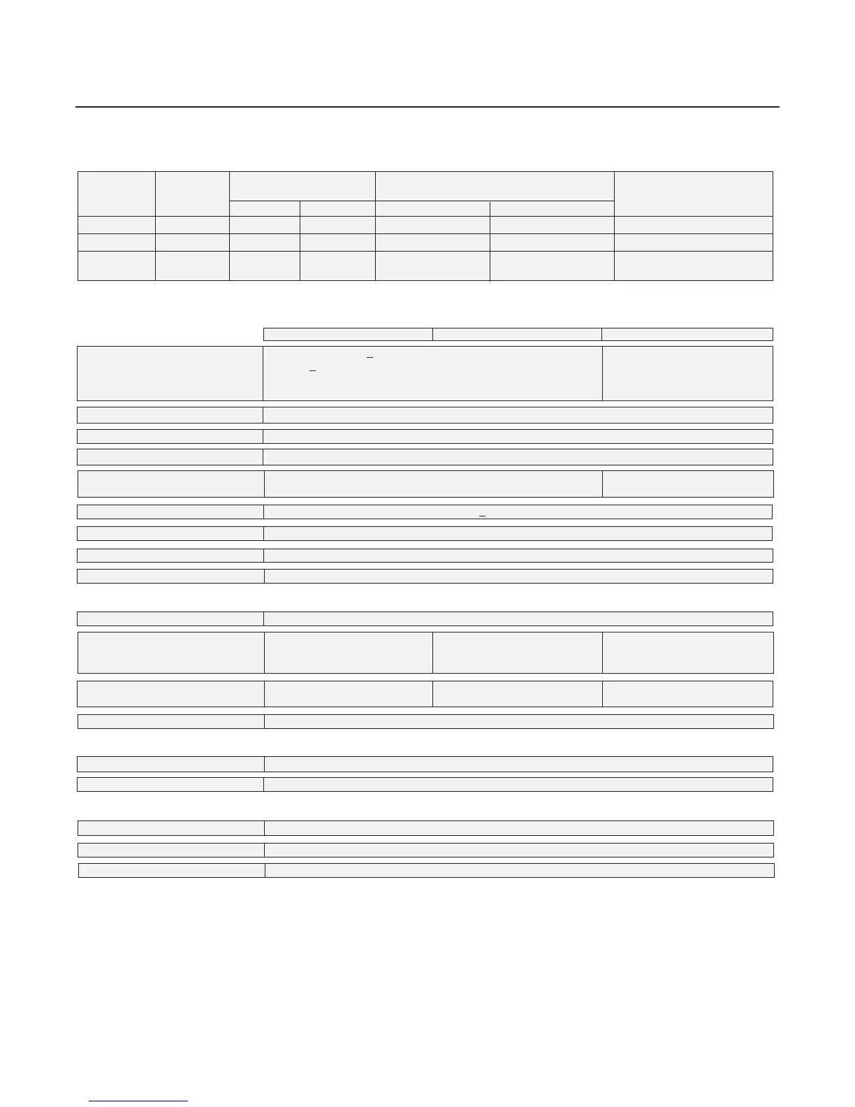
Table 1-1 SLA5800 Series Specifications
SLA5850/60SLA5850/60
SLA5850/60SLA5850/60
SLA5850/60
SLA5851/61SLA5851/61
SLA5851/61SLA5851/61
SLA5851/61
SLA5853/63SLA5853/63
SLA5853/63SLA5853/63
SLA5853/63
* Response time can be improved upon request
Flow Ranges and PrFlow Ranges and Pr
Flow Ranges and PrFlow Ranges and Pr
Flow Ranges and Pr
essuressur
essuressur
essur
e Ratings:e Ratings:
e Ratings:e Ratings:
e Ratings:
Mass FlowMass Flow
Mass FlowMass Flow
Mass Flow
Mass FlowMass Flow
Mass FlowMass Flow
Mass Flow
Flow RangesFlow Ranges
Flow RangesFlow Ranges
Flow Ranges
Pressure UnitPressure Unit
Pressure UnitPressure Unit
Pressure Unit
PED Module HPED Module H
PED Module HPED Module H
PED Module H
ControllerController
ControllerController
Controller
MeterMeter
MeterMeter
Meter
N2 Eq. RatingsN2 Eq. Ratings
N2 Eq. RatingsN2 Eq. Ratings
N2 Eq. Ratings
psi/barpsi/bar
psi/barpsi/bar
psi/bar
CategoryCategory
CategoryCategory
Category
ModelModel
ModelModel
Model
ModelModel
ModelModel
Model
Min. F.S.Min. F.S.
Min. F.S.Min. F.S.
Min. F.S.
Max. F.S.Max. F.S.
Max. F.S.Max. F.S.
Max. F.S.
StandardStandard
StandardStandard
Standard
OptionalOptional
OptionalOptional
Optional
SLA5850 SLA5860 0.003 50 lpm 1500 psi/103 bar 4500 psi/310 bar SEP
SLA5851 SLA5861 15 200 lpm* 1500 psi/103 bar NA** SEP
SLA5853 SLA5863 100 2500 lpm 1000 psi/70 bar NA 1 for all 150 lb flanges
2 for all other connections
* 600 lpm of H2 possible with decreased accuracy ** 4500 psi/310 bar available as a special on the SLA5861 only
> 40 psig inlet required for flows greater than 100 lpm.
* Alarm modes are dependent on the communications interface. These are described in the corresponding digital communication interface manual.
** Hazardous area certifications have a temperature range limitation of 0-65°C.
PerformancePerformance
PerformancePerformance
Performance
Flow AccuracyFlow Accuracy
Flow AccuracyFlow Accuracy
Flow Accuracy
+0.9% of S.P. (20-100% F.S.), ±0.9% of S.P. (20-100% F.S.),
+0.18% of F.S. (2-20% F.S., 1-20% F.S. from 1-50 lpm)
±0.18% of F.S. (2-20% F.S.) up to 1100 lpm
±1.0% of F.S. from 1100 lpm
up to 2500 lpm
Control RangeControl Range
Control RangeControl Range
Control Range
100:1 for F.S. from 1-50 lpm (50:1 for all other F.S. flows)
Repeatability & ReproducibilityRepeatability & Reproducibility
Repeatability & ReproducibilityRepeatability & Reproducibility
Repeatability & Reproducibility 0.20% S.P.
LinearityLinearity
LinearityLinearity
Linearity Included in accuracy
Response Time (Response Time (
Response Time (Response Time (
Response Time (
Settling Time withinSettling Time within
Settling Time withinSettling Time within
Settling Time within < 1 second < 3 seconds
±2% F.S. for 0-100% command step)*±2% F.S. for 0-100% command step)*
±2% F.S. for 0-100% command step)*±2% F.S. for 0-100% command step)*
±2% F.S. for 0-100% command step)*
Zero StabilityZero Stability
Zero StabilityZero Stability
Zero Stability <
+ 0.2% F.S. per year
Temperature CoefficientTemperature Coefficient
Temperature CoefficientTemperature Coefficient
Temperature Coefficient
Zero: <0.05% of F.S. per °C. Span: <0.1% of S.P. per °C
Pressure CoefficientPressure Coefficient
Pressure CoefficientPressure Coefficient
Pressure Coefficient ±0.03% per psi (0-200 psi N2)
Attitude SensitivityAttitude Sensitivity
Attitude SensitivityAttitude Sensitivity
Attitude Sensitivity
<0.2% F.S. maximum deviation from specified accuracy after re-zeroing
RatingsRatings
RatingsRatings
Ratings
Operating Temperature RangeOperating Temperature Range
Operating Temperature RangeOperating Temperature Range
Operating Temperature Range -14 to 65
o
C (7 to 149
o
F)**
Minimum Pressure DifferentialMinimum Pressure Differential
Minimum Pressure DifferentialMinimum Pressure Differential
Minimum Pressure Differential 5 psi/0.35 bar 10 psi/0.69 bar Min.: 7.5 psi/0.52 bar at 500 lpm
(Controllers)(Controllers)
(Controllers)(Controllers)
(Controllers) Min.: 14.5 psi/1.00 bar at 1000 lpm
Min.: 35.0 psi/2.41 bar at 2500 lpm
Maximum Pressure DifferentialMaximum Pressure Differential
Maximum Pressure DifferentialMaximum Pressure Differential
Maximum Pressure Differential Application specific up to 50 psi/3.45 bar 300 psi/20.0 bar
(Controllers)(Controllers)
(Controllers)(Controllers)
(Controllers) 1500 psi/103.4 bar
Leak Integrity (external)Leak Integrity (external)
Leak Integrity (external)Leak Integrity (external)
Leak Integrity (external) 1x10
-9
atm. cc/sec He
MechanicalMechanical
MechanicalMechanical
Mechanical
Valve TypeValve Type
Valve TypeValve Type
Valve Type Normally Closed, Normally Open, Meter
Primary Wetted MaterialsPrimary Wetted Materials
Primary Wetted MaterialsPrimary Wetted Materials
Primary Wetted Materials 316L Stainless Steel, High Alloy Stainless Steel, Viton
®
fluoroelastomers, Buna-N, Kalrez
®
, Teflon
®
/Kalrez
®
, and EPDM
DiagnosticsDiagnostics
DiagnosticsDiagnostics
Diagnostics
Status LightsStatus Lights
Status LightsStatus Lights
Status Lights MFC Health, Network Status
Alarms*Alarms*
Alarms*Alarms*
Alarms*
Sensor Output, Control Valve Output, Over Temperature, Power Surge/Sag, Network Interruption
Diagnostic/Service PortDiagnostic/Service Port
Diagnostic/Service PortDiagnostic/Service Port
Diagnostic/Service Port RS485 via 2.5mm jack