3-46
Confidential
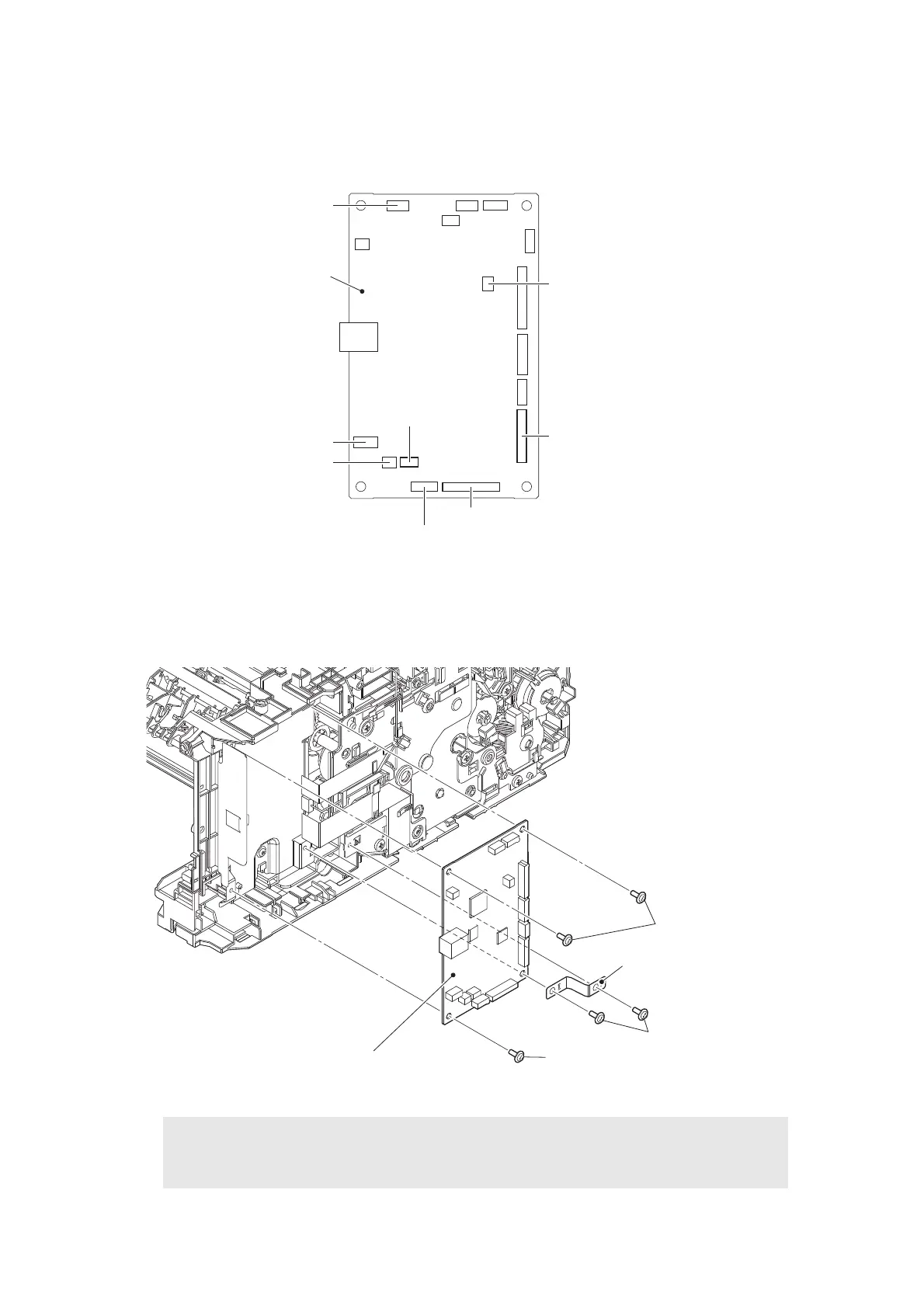
9.20 Main PCB ASSY
(1) Disconnect all harnesses and flat cables from the Main PCB ASSY.
Fig. 3-41
Harness routing: Refer to “3. Top side of the machine”, “4. Frame L unit (Manual feed models)”.
(2) Remove the two Screw cup M3x8 (black) screws, and remove the Main PCB FG plate 1.
(3) Remove the three Screw cup M3x8 (black) screws, and remove the Main PCB ASSY.
Fig. 3-42
Assembling Note:
• After the replacement, refer to “1. IF YOU REPLACE THE MAIN PCB ASSY” in
Chapter 4 to enter the adjusted value of the Main PCB ASSY.
Front cover sensor harness
Cartridge sensor harness
(For models without Toner box)
Paper feed motor flat cable
Paper feed sensor harness
LVPS harness
Eject sensor flat cable
T1 clutch harness
Registration
clutch harness
Main PCB ASSY
Screw cup M3x8 (black)
Screw cup M3x8 (black)
Main PCB ASSY
Main PCB FG plate 1
<Back side>
Screw cup M3x8 (black)

 Loading...