23 LS2-B891, LT2-B892
8. ADJUSTING THE NEEDLE STOP POSITION (-705)
8. EINSTELLEN DER NADELSTOPPOSITION (-705)
8. REGLAGE DE LA POSITION D'ARRET DE L'AIGUILLE (-705)
8. AJUSTE DE POSICION DE PARADA DE LA AGUJA (-705)
8. ADJUSTING THE NEEDLE STOP POSITION (-705)
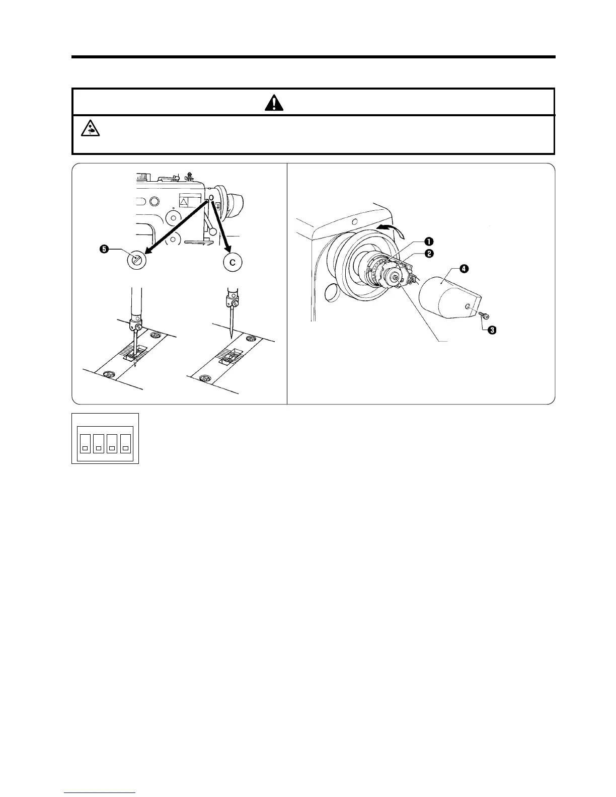
The synchronizer detects the needle position by means of two discs q and w.
■ Adjusting the needle up stop position
When the sewing machine stops in the needle up stop position and the treadle is pressed back, the “C” mark should be visible in
the window of the belt guard.
* If the “C” mark is not visible in the window of the belt guard, thread trimming errors may occur, so adjust by the following
procedure.
1. Turn off the power switch.
2. Loosen the screw e, and then remove the cover r.
3. When the needle up stop position disc q is turned in the same direction as the direction of machine pulley rotation, the “C” mark
will stop in a position before the position before adjustment. If the disc q is turned in the opposite direction, the “C” mark will stop
in the position after the position before adjustment.
■ Adjusting the needle down stop position (thread trimming signal position)
When the sewing machine stops in the needle down stop position, the set screw t should be visible in the window of the belt
guard.
* If the set screw t is not visible in the window of the belt guard, lower thread take-up errors may occur, so adjust by the following
procedure.
1. Turn off the power switch.
2. When the needle down stop position disc w is turned in the same direction as the direction of machine pulley rotation, the set
screw t will stop in a position before the position before adjustment. If the disc w is turned in the opposite direction, the set
screw t will stop in the position after the position before adjustment.
3. After adjusting, install the cover r with the screw e.
Caution:
Make sure that all DIP switches (DIPA) inside the motor control box have been set to the OFF position before
carrying out the following adjustment. (Refer to the separate instruction manual for the motor.)
●
If the power switch and air need to be left on when carrying out some adjustment, be extremely careful to observe all
safety precautions.
CAUTION
Direction of machine pulley rotation
There is no need to loosen
this screw when turning the
discs.
DIPA
OFF
3
4
1
2
Needle up stopNeedle down stop