3-67
Confidential
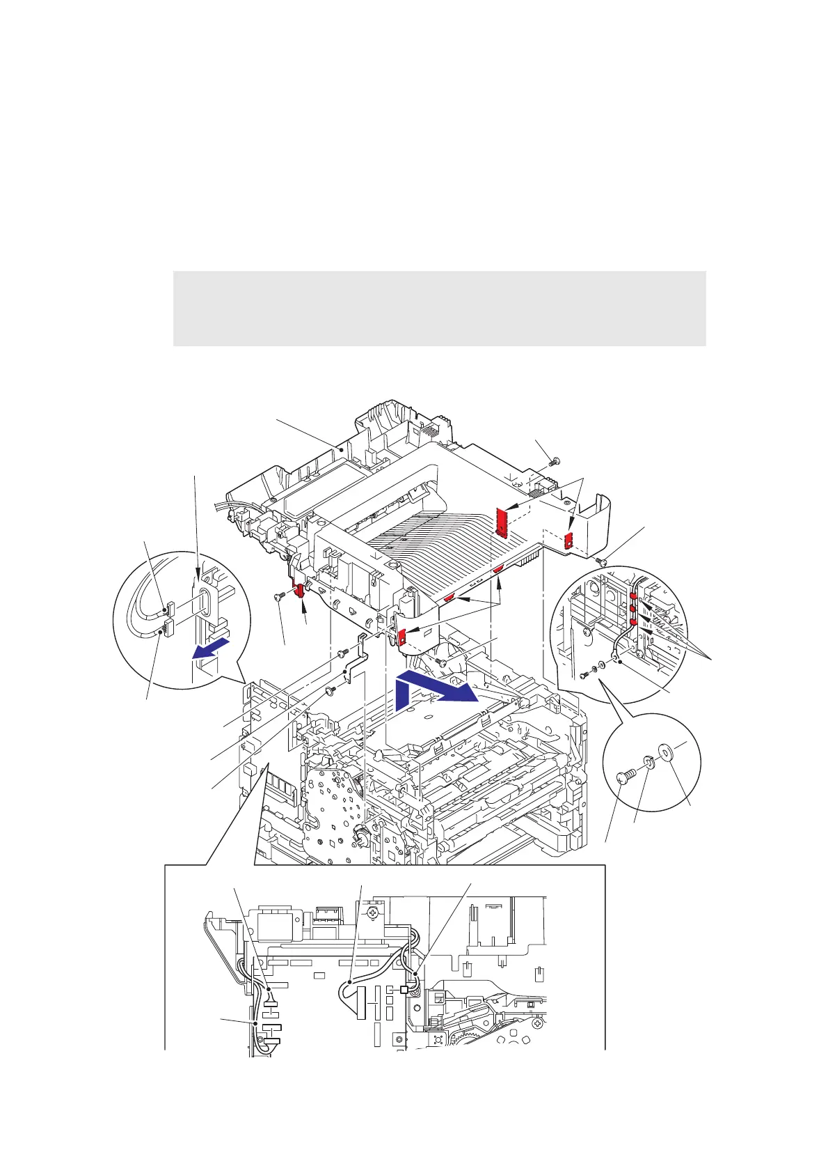
9.12 Joint cover
(1) Remove the screw pan M4x8, washer spring 2-4, washer 5 to remove the NCU earth
harness from the machine, and release the NCU earth harness from the securing fixtures.
(2) Disconnect the wireless LAN harness, USB host harness, speaker harness, and NCU
harness from the main PCB.
(3) Pull out the wireless LAN harness and the USB host harness from the main PCB shield
calking ASSY.
(4) Remove the taptite cup S M3x8 SR screw and taptite bind B M4x12 screw one at a time to
remove the earth plate.
(5) Remove the four taptite bind B M4x12 screws.
(6) Release the six hooks, and slide the joint cover in the direction of the arrow to remove it.
Fig. 3-92
Harness routing: Refer to “1.Main PCB ASSY” and “11.Main frame R” .
*1
For touch panel models, the taptite bind B M4x12 screw has already been
removed on earlier process.
*2
South Korean models are not equipped with the earth plate, taptite cup S M3x8
SR screw, and taptite bind B M4x12 screw.
Joint cover
Taptite bind B M4x12
Main PCB shield
calking ASSY
USB host
harness
Wireless LAN harness
Taptite bind
B M4x12
Hooks
Screw pan M4x8
NCU earth
harness
Guides
Taptite bind
B M4x12
Hooks
Speaker harness
USB host harness
Taptite
bind B
M4x12
Wireless
LAN
harness
NCU harness
*2
Taptite cup S M3x8 SR
*2
Earth plate
Hook
Washer spring 2-4
Washer 5
*1
*2
Taptite bind B M4x12
 Loading...