8. ELECTRICAL MECHANISM
198
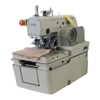
RH-9820
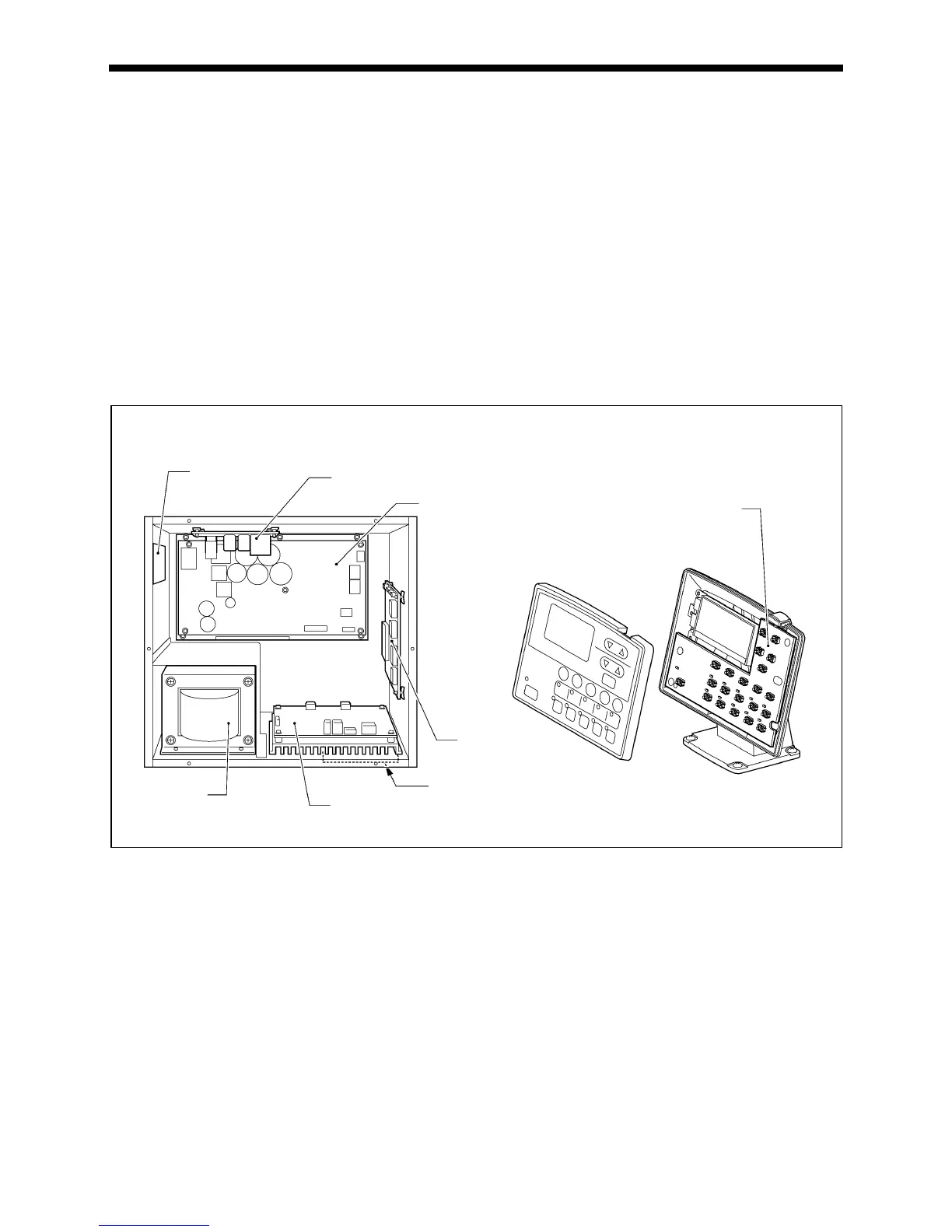
8-2. Inside the control box and operation panel structure
Main P.C. board
Secured to the side. This is the P.C. board that controls sewing machine operation.
PMD P.C. board
Secured to the base plate. This P.C. board drives the pulse motors and solenoids.
Power supply motor P.C. board
Secured to the rear. This P.C. board generates the voltages that are required for control, and drives the upper shaft motor.
There are 8 fuses on this P.C. board.
Filters (3 places)
The filters at the air intake slots in the cover and control box (2 places) should be cleaned about once a month.
Conversion transformer (Two types are used depending on the power supply voltage specifications.)
This breaks down the power supply voltage into the voltages that are required for control operations.
NF P.C. board
This eliminates the electrical interference that is generated by the power supply line.
Panel P.C. board
Secured to the inside of the operation panel. This P.C. board is used for displaying the sewing machine status and for input
operations.
Control box
Operation panel
Filter
NF P.C. board
Conversion
transformer
PMD P.C. board
1199B 0692B
Panel P.C. board
Power supply
motor P.C. board
Main P.C. board
Filter
 Loading...