ADJUSTMENTS
Lower Netting.
Lower Netting Clamp Solenoid.
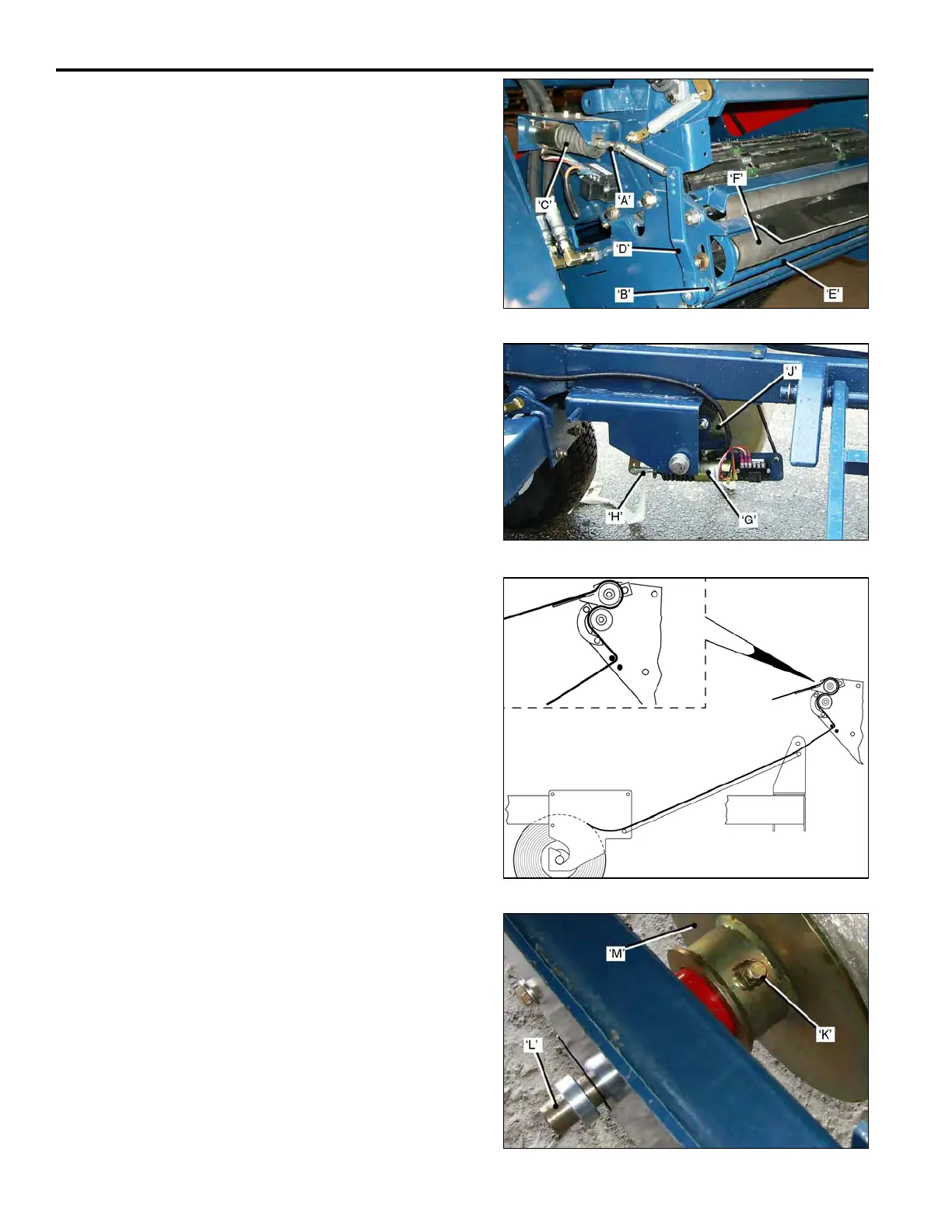
• The Solenoid Yoke ‘A’, is adjusted to allow free
play in the clamp mechanism ‘B’.
• When the Solenoid ‘C’, is activated the Lever ‘D’,
is pulled forward, and the Clamp Bar ‘E’, clamps
the netting against the Roller ‘F’.
Lower Netting Brake.
• The Lower Netting Brake Solenoid ‘G’, activates
at the same time as the above Clamp Solenoid.
• The Solenoid Yoke ‘H’, is adjusted so that there is
minimum free-play in the linkage, and no ‘drag’ on
the Brake ‘J’, when the solenoid is de-activated.
When both Solenoids are activated, the Netting Clamp and
the Brake are ‘On’, the Roll-Up Unit will swing around and
cut the netting.
Lower Netting Feed Path.
Before operating, the netting must be manually fed through
the Rollers as illustrated.
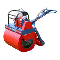
Installing new Lower Reel of Netting.
• Loosen the Lock-bolt ‘K’.
• Lift the Reel Shaft ‘L’, out of the frame and carefully
lower it, sufficient to allow the Netting Retainer ‘M’, to
be removed.
• Install the new reel of netting onto the Shaft, refit the
Netting Retainer, tighten the Lock-bolt. Lift the Shaft
back into the frame.
3-22