MAINTENANCE PROCEDURES
5. If a new belt was installed, adjust
the belt height. Refer to
DRIVE
BELT HEIGHT ADJUSTMENT
be-
low.
6. Install belt guard, refer to
DRIVE
BELT GUARD INSTALLATION
.
7. Close side panel, refer to
SIDE
PANELS
in
CONTROLS, INSTRU-
MENTS AND EQUIPMENT
.
DriveBeltHeightAdjustment
The drive belt height must be checked
every time a new belt is installed.
To adjust the drive belt height, proceed
as follows:
1. Remove the tether cord cap from
engine cut-off switch.
2. Open LH side panel, refer to
SIDE
PANELS
in
CONTROLS, INSTRU-
MENTS AND EQUIPMENT
subsec-
tion.
3. Remove belt guard, refer to
DRIVE
BELT GUARD REMOVAL
.
4. Loosen the clamping bolt.
mmo2011-003-010_a
ALUMINUM ADJUSTER HUB
1. Adjuster hub
2. Clamping bolt
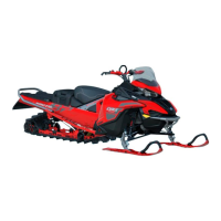
5. Using the suspension adjustment
tool provided in the tool kit, turn the
ring 1/4 turn at a time then rotate the
driven pulley to properly set the belt
between the pulley sheaves.
mmo2011-003-011_a
ALUMINUM ADJUSTER HUB
1. Suspension adjustm ent tool
NOTE: The adjustment ring has left
hand treads.
Belt without External Cogs
Repeat step 5 until the external sur-
face of drive belt exceeds driven pulley
edge by 0mm.
mmr2009-081-001_a
PRELIMINARY SETTING
A. 0mm
Be lt with Ex ternal Cogs
Repeat step 5 until the bottom of
grooves on the external side of drive
belt are flush with the driven pulley
edges.
mmr2008-040-108_a
PRELIMINARY SETTING
1. Driven pulley edge
2. External drive b elt grooves
90
______________