MAINTENANCE PROCEDURES
1
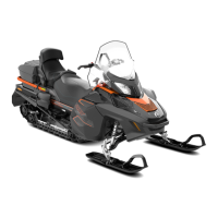
A33D19A
TYPICAL
1. Notch
There are 6 positions numbered 1 to 6.
Each position modifies maximum en-
gine RPM by approximately 200 RPM.
Lower position numbers decrease en-
gine RPM in steps of 200 RPM and
higher position numbers increase it in
steps of 200 RPM.
Example:
Calibration screw is set at position
4 a nd is changed to position 6 . So
maximum engine RPM is increased
by 400 RPM.
Procedure
Just loosen lock nut enough to pull
calibratio n screw p artially out an d
adjust to desired position. Do not
completely remove the lock nut.
Torque lock nuts to 10 N•m ± 2 N•m
(89 lbf•in ±18lbf•in).
NOTICE
Do not completely re-
move calibration screw otherwise
internal washers will fall off. Al-
ways adjust all 3 calibra tion screws
and make sure they are all set to the
same position.
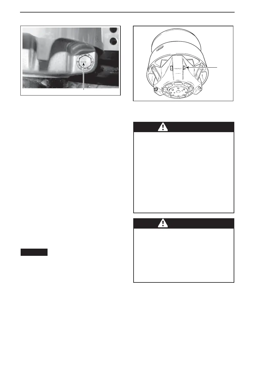
A16D0HA
1
TYPICAL
1. Loosen just enough to permit rotating of
calibrate screw
WARNING
NEVER disassemble or modify the
drive pulley.
Improper assembly or modifica-
tions could c ause the pulley to ex-
plode violently under the stress
generated by the high rotational
speed.
See your Lynx dealer to maintain
or service the drive pulley. Im-
proper servicing or maintenance
may affect performance and re-
duce belt life. Always respect
maintenance schedules.
WARNING
NEVER operate engine:
– Without shields and belt guard
securely installed.
– With hood and/or side panels
opened or removed.
NEVER attempt to make adjust-
ments to moving parts while en-
gine is running.
92
______________