B.U.D.S. PROGRAMMING
tbl2013-009-044_a
Connecting the PC to the
Vehicle
REQUIRED TOOLS
MPI-2 DIAGNOSTIC CABLE
(P/N 710 000 851)
MPI-2 INTERFACE CARD
(P/N 529 036 018)
1. Locate the 6-pin diagnostic connector, refer to
DIAGNOSTIC CONNECTOR LOCATION
.
2. Disconnect the 6-pin diagnostic connector from
its holder (protective cap).
3. Connect one end of the MPI-2 diagnostic cable
to the vehicle connector.
tbl2013-009-045_a
4. Connect the other end of diagnostic cable to the
MPI-2 interface card.
vdd2006-001-151
DIAGNOSTIC CABLE CONNECT ED TO MPI-2 INTERFACE CARD
NOTE: An optional MALE-FEMALE EXTENSION SE-
RIAL CABLE (P/N DB9)
available at electronic retail
outlets can be used between diagnostic cable and
MPI-2 interface. Do not exceed 7.6 m (25 ft).
529035697
OPTIONAL MALE-FEMALE EXTENSION SERIAL CABLE
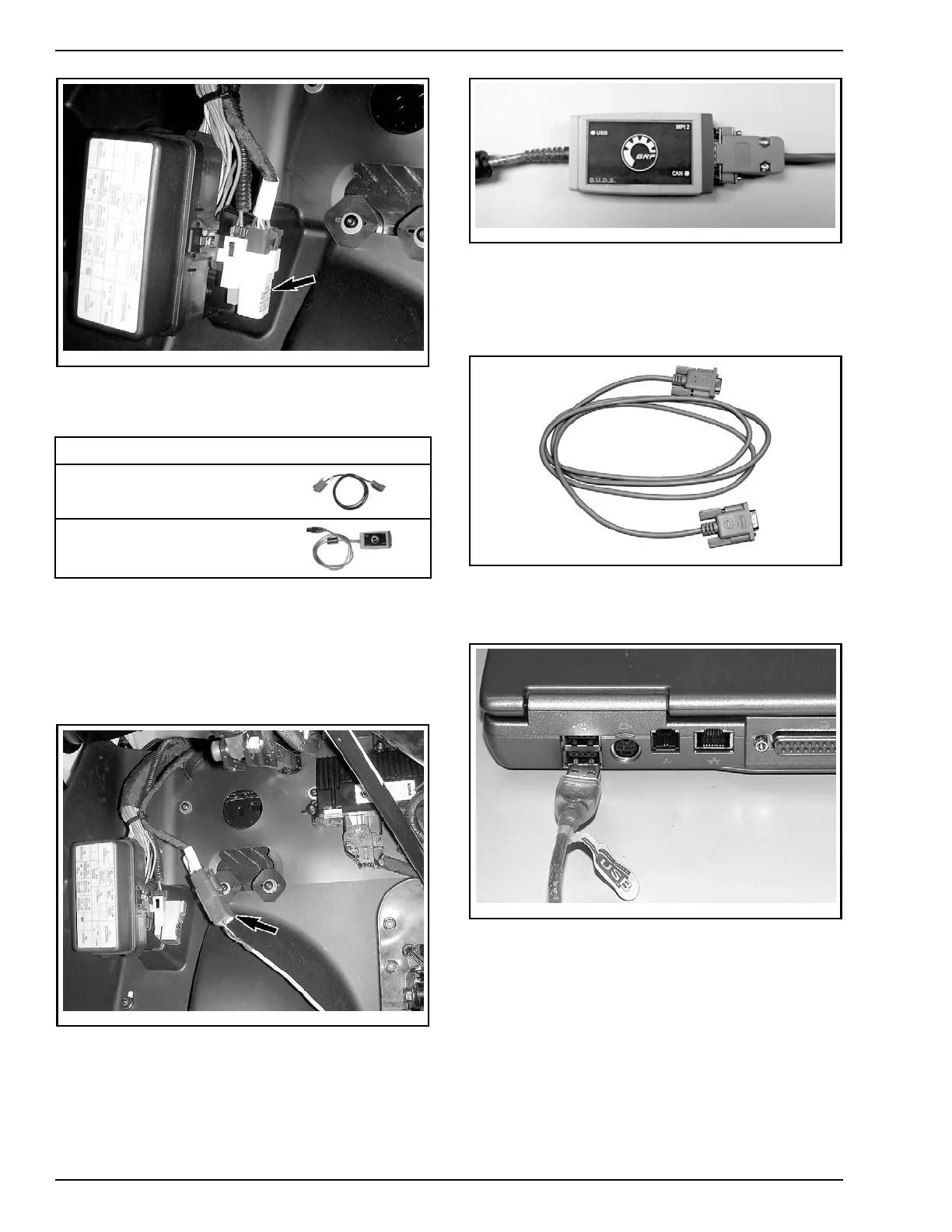
5. Connect the MPI-2 interface card to the USB
port of a PC (personal computer).
mmr2006-079-200
MPI-2 INTERFACE CARD CONNECTED TO USB PORT
How to Establish
Communication Using B.U.D.S.
Software
NOTE: Before beginning, check if the latest ver-
sion of B.U.D.S., available on BOSSWeb for this
vehicle, is installed on your computer.
22 / 34 2014-1 PREDELIVERY