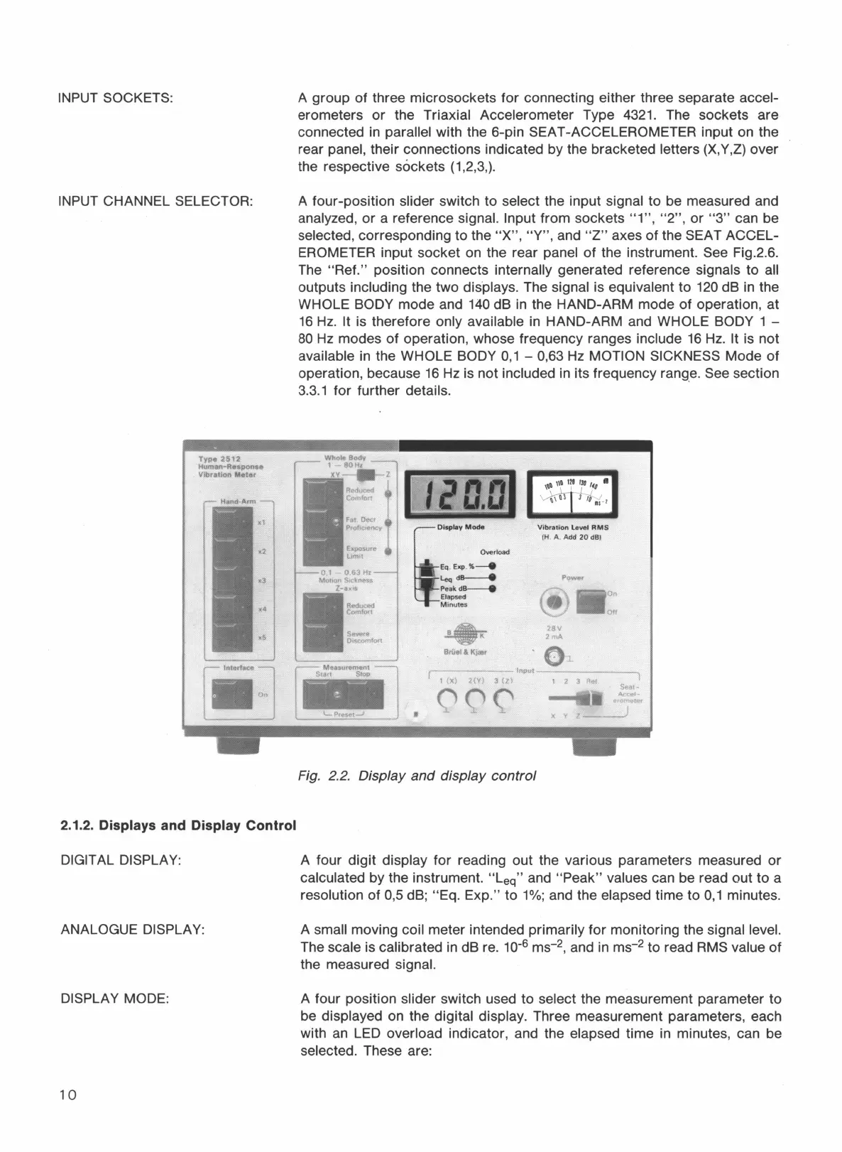
INPUT SOCKETS:
INPUT CHANNEL SELECTOR:
Type
2512
Human-Re•ponse
VlbraUon
Meter
2.1.2. Displays and Display Control
DIGITAL DISPLAY:
ANALOGUE DISPLAY:
DISPLAY MODE:
10
A group
of
three microsockets
for
connecting either three separate accel-
erometers
or
the Triaxial Accelerometer Type 4321. The sockets are
connected
in
parallel with the 6-pin SEAT-ACCELEROMETER input on the
rear panel, their connections indicated by the bracketed letters (X,Y,Z) over
the respective sockets (1,2,3,).
A four-position slider switch to select the input signal to be measured and
analyzed,
or
a reference signal. Input from sockets "1
",
"2",
or
"3"
can be
selected, corresponding to the
"X",
"Y",
and
"Z"
axes
of
the SEAT ACCEL-
EROMETER input socket on the rear panel
of
the instrument. See Fig.2.6.
The
"Ref."
position connects internally generated reference signals to all
outputs including the two dis.plays. The signal is equivalent to
120
dB in the
WHOLE BODY mode and
140
dB in the HAND-ARM mode
of
operation, at
16
Hz.
It is therefore only available
in
HAND-ARM and WHOLE BODY 1 -
80
Hz
modes
of
operation, whose frequency ranges include
16
Hz.
It is not
available in the WHOLE BODY
0,
1 - 0,63
Hz
MOTION SICKNESS Mode
of
operation, because
16
Hz
is not included in its frequency rang_
e.
See section
3.3.1
for further details.
01
-
0,63
Hz
Monon s,ckness
•
Z-a;~:uced
Comfort
Severe
Discomfort
Measurement
lilil
LPreset....1
I
l
Oisplay
Mode
Overload
Eq.
Exp
.
%--4t
leq
ds----e
Peakds--e
Elapsed
Minut
es
Briiel & Kla,r
Vibration
level
RMS
(H
. A . Add
20
dBi
Power
@•::
28V
2mA
,-------
Input------
1
(X)
2(Y)
3
(Zi
1 2 3 Rel
•
QQ('
X y
Fig. 2.2. Display
and
display control
A four
digit
display
for
reading out the various parameters measured
or
calculated by the instrument. "Leq" and
"Peak"
values can be read out
to
a
resolution
of
0,5 dB; "Eq. Exp." to
1%;
and the elapsed time to
0,
1 minutes.
A small moving coil meter intended primarily
for
monitoring the signal level.
The scale is calibrated in dB re.
10-
6
ms-
2
,
and
in
ms-
2
to read RMS value
of
the measured signal.
A four position slider switch used to select the measurement parameter to
be displayed on the digital display. Three measurement parameters, each
with
an
LED overload indicator, and the elapsed time
in
minutes, can be
selected. These are:

 Loading...