7.
Set up the
2512
to perform the required measurement as described in section 3.4.
8.
Switch on the level recorder by pressing
in
the PAPER DRIVE push-button to start
recording, and press again to release it and thus stop the recording.
For further details on the use and operation
of
the level recorders, their Instruction Manuals
should be consulted.
Note: It is also possible to record the time history
of
the signal from the OUTPUT
TO
EXT. FIL-
TER
socket in the MOTION SICKNESS mode using the above technique, because the Level
Recorder Type 2306 will faithfully record frequencies up
to
1,6
Hz
in
the
"DC
Lin"
position,
covering the entire frequency range
of
MOTION SICKNESS measurements.
4.3. USE WITH THE
ST
A TIS TIC
AL
NOISE LEVEL ANALYZER TYPE 4426
34
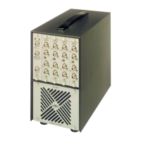
The Noise Level Analyzer Type 4426 is a statistical analyzer suitable
for
use with the Type
2512, which can easily connected and calibrated. A special transparent scale (SC 2363), which
can be laid over the level recorder output from the 4426 enables the statistical distribution to
be found and the
LN
values (the vibration level exceeded for N %
of
the measurement time) to
be read directly from the cumulative distribution curve. The procedure for using the 2512 with
the Noise Level Analyzer Type 4426 and the Portable Level Recorder Type 2306, see Fig.4.4., is
described below:
Remote
AO
0034
_
___._
_
__,
Control
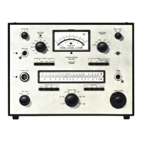
Portable Level
Recorder
Type 2306
Human-
Response
Vibration Meter
Type2512
Noise Level
Analyzer
Type
4426
AO 0087
8 10425
Fig. 4.4. Statistical analysis
of
vibration using the Noise Level Analyzer
Type_
4426
and
Portable Level Recorder Type 2306 with the 2512
1.
Connect the
DC
OUTPUT socket on the rear panel
of
the Type 2512 to the DIRECT input
socket on the rear panel
of
the Type 4426 using a BNC to BNC cable AO 0087, and ensure
that the INPUT SELECTOR control on the 4426 is switched to the
"DC
O - 6,4
V"
position.
2.
On
the 2512:
a.
Set the FILTER SELECTOR on the rear panel to the "Weighting Filter
In,
Ext. Filter
Out"
position.
b.
Set the INPUT SELECTOR on the instrument's front panel to the
"Ref."
position.
c.
Ensure that any
of
the WHOLE BODY 1 -
80
Hz
or
HAND - ·
ARM
modes are selected,
giving a
120
dB npminal output, (140 dB for HAND - ARM), which is indicated on the
analogue display.

 Loading...