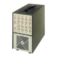
To replace the fuse it is necessary to gain access by sliding back the top panel (see Fig.3.8.),
after removing the two screws which hold it to the rear panel. The fuse can then be seen at the
front
of
the instrument, can be removed from its clip, and a new one inserted. The fuse rating is
800
mA.
3.3. CALIBRATION
The Type 2512 is intended primarily to be used with one of the Br0el
& Kjrer range of Uni-Gain
Accelerometers which have a unified sensitivity of 1
pC/ms-
2
(
±
2%).
The special Seat-
Accelerometer Type 4322 for whole-body measurements on seated persons is a triaxial
accelerometer, all
of
whose individual sensitivities are unity within the stated tolerances. With
any
of
these accelerometers, the Type 2512 forms a compatible precalibrated measurement
system which is easy to set up and operate both in the field and in the laboratory. The need for
laborious calibration procedures is thus virtually eliminated, and the setting up procedure is
effectively reduced to
an
instrument check, using the internal reference signal. There is no
sensitivity adjustment on the instrument, nor should one be required during normal use. If a
calibration check such as either of those in the following sections shows that the instrument is
not operating correctly, e.g. the counting rates are not within the limits stated, then the
instrument should be serviced.
The most straightforward method of checking is to use the instrument's internal reference
signal. For
or
a more thorough calibration, including a check
of
the accelerometer and its
connections to the Type 2512, the Accelerometer Calibrator Type
4291
can be used, and, being
powered from internal batteries, is equally suitable for field or laboratory use. This instrument
supplies
an
accurate vibration level of
10
ms-
2
(1
g on early models) at 79,6
Hz
(500
radians-
.sec-1) directly to the accelerometer. Both methods are described in the following sections.
The two checking procedures are described in the following sections.
3.3.1. Calibration using the Internal Reference Signal
The internal reference signal is obtained by placing the INPUT CHANNEL SELECTOR in the
"Ref."
position. A
16
Hz
reference signal is then applied to the whole
of
the measurement and
analysis chain after the normal input stage. The actual level
of
the reference signal is controlled
by the type
of
measurement selected, so that the attenuation of the frequency weighting curve
at
16
Hz
for that measurement is compensated for by a corresponding increase in the
reference
signal
input
level.
The
resulting
level
after
passing
through
the
weighting
filter,
Log
RMS detector, and
Leq
calculator is therefore always constant for a given measurement mode.
This level is 1
ms-
2
or
120
dB (re
10-6
ms-
2
)
for whole-body vibration measurements and
10
ms-
2
or
140
dB (re
10-6
ms-
2
) for hand-arm vibration measurements.
It should be noted that the internal reference signal, at
16
Hz,
lies outside the frequency range
of the Motion Sickness measurement region and can not therefore be used for checking
or
calibrating this mode
of
operation of the instrument.
The procedure is as follows:
1.
Select
"Ref"
on the INPUT CHANNEL SELECTOR. The needle
of
the analogue meter
should now come to the middle of the scale indicating 1
ms-
2
(or
120
± 0,5 dB).
2.
"Preset" the instrument by pressing both
of
the MEASUREMENT pushkeys simultaneous-
ly. The LEDs in both keys will come on to indicate that the registers have been cleared and
that the instrument has been initialized and
ready to begin a new measurement. Only in
this state can the measurement mode be selected.
23

 Loading...