MEASUREMENT:
INTERFACE SWITCH:
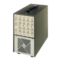
2.2. REAR PANEL
BATTERY COVER:
RELEASE SCREW:
Two pushkeys with integral LED indicators
for
starting, stopping and reset-
ting the measurement.
"Start" starts a measurement,
or
continues a measurement which was
temporarily halted using the
"Stop"
pushkey.
"Stop" stops the measurement in progress. It may be continued by press-
ing
"Start",
or
the internal registers can be cleared and a completely new
measurement can be initiated by pressing the
"Start"
and
"Stop"
pushkeys
simultaneously, the
"Preset"
position.
"Preset" is the only position which allows the measurement mode to be
altered, the HAND-ARM, LIMIT SELECTOR and AXIS SELECTOR switches
are otherwise locked in the previously selected positions. The LEDs in both
pushkeys will light when pressed simultaneously to indicate that a reset has
occured, that the instrument has been initialized, that a new measurement
mode can be selected, and that a new measurement can be begun by
pressing
"Start".
In
the
"Preset"
mode, the time constant is very short
(0,
125
s in the HAND-ARM and WHOLE BODY 1 -
80
Hz
modes, and 0,6 s in
the WHOLE BODY
0,
1 - 0,63
Hz
MOTION SICKNESS mode) to give a short
settling time when changing measurement mode. It may also be used when
recording on a level recorder to obtain an output with relatively short time
constant.
A single pushkey with integral LED indicator, which lights when the switch is
in the
"On"
position and the interface is connected. The instrument can
then transmit the full data list at intervals
of
2 s
or
greater.
Ext
.
Power
Supply
• Charge -
+6
Vto
l2V
+
15V
I
..
i ..
F.atteries Interface B
us
OEC)
Seat-
Accelerometer
•
O~J 8
87654321
7
I : Reset o: Accumulate
t :
Printer
0 : ca1culator
Weight
in
g Ext.
Filter Filter
Out
In
In
In
In
Out
Output
to
Input
from
@@
1 : Ton O: Addressable
::
MSB
l Device
A2.
Address
At
LS8
••
••
*CAUTION
CHARGE VOLTAGE
MUST
ONLY
BE
APPLIED
WHEN USING RECHARGEABLE BATTERIES
Fig.
2.4.
Rear Panel
A knurled screw which allows the side panel to be removed to give access
to the battery compartment
for
installation
of
new batteries. See section
3.1.
13

 Loading...