INTERFACE
BUS
(IEC):
ADDRESS SWITCH:
SUBSWITCH
8:
SUBSWITCH
7:
SUBSWITCH
6:
SUBSWITCHES
5 -
1:
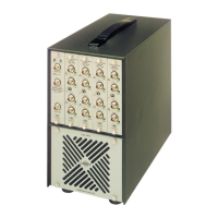
DC OUTPUT:
25-pin socket
for
direct connection
of
the Type 2512 to
an
instrument with
an
interface bus such as the Alphanumeric Printer Type 2312 using the B &
K cable AO 0194 (AO 0184
for
early models
of
the 2312, before serial
number 920925). Complete details are given
in
Section
4.1.
A set
of
eight subswitches each with two positions; the top
of
the switch
pressed
in
(1),
and the bottom
of
the switch pressed in
(0).
Controls whether
or
not the current measurement is to be continued
or
a
new measurement is to be started when data transmission takes place.
"1:
Reset" - As soon as data transmission begins, the registers
of
the 2512
are cleared and a new measurement is begun.
"0: Accumulate" - The current measurement is continued when a data
transmission command is received.
Controls the format of the transmitted data.
"1: Printer" - Primarily for use with the Alphanumeric Printer Type 2312.
The data is accompanied by explanatory text. See Section
4.1.
for further
details.
"0: Calculator"- Output is
in
accordance with IEC 625-2 without explana-
tory text. Primarily intended for transmission to a calculator
for
further
processing
or
to a digital cassette recorder. For further details see Section
4.1.
Controls the mode
of
operation of the interface.
"1: Ton" - Talk only - Enables the 2512 to output data to a listener without
the use
of
an
external controller. Primarily for use with the Alphanumeric
Printer Type 2312
or
Digital Cassette Recorder Type
7400.
"0:
Addressable" - Allows the 2512 to be addressed by
an
external
controller, e.g. a desk-top calculator, using a unique name which is deter-
mined by the settings
of
the next 5 switches, numbers 5 to
1.
These
switches
are
the
last
five
bits
of
a
7-bit
ASCII
coded
word,
the
first
two bits
of
which are assumed to be
"1"
and "O" respectively. They select
the address code
for
the 2512
in
an
addressable system and are preset at
the factory to binary 01100, which corresponds to the alphanumeric charac-
ter
"L".
Switch
"5"
sets the most significant bit (MSB)
AS,
and switch
"1"
selects the least significant bit (LSB) A
1.
Depressing the upper part
of
the
switch corresponds to
1,
and pressing the lower part
of
the switch corre-
sponds to a
0,
as indicated alongside the switch. They allocate a binary
number to the 2512 corresponding to its address in the system. They have
no effect unless the INTERFACE switch on the front panel is
"On".
A BNC socket providing a DC signal from the logarithmic RMS detector.
Output level is
100
mV
/dB
with O V equivalent to
100
dB
in
the WHOLE
BODY mode and
120
dB in HAND-ARM mode. Minimum load impedance is
5
kQ.
15

 Loading...