42
8.
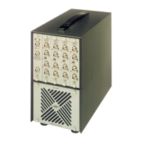
Set the FILTER SELECTOR SWITCH on the rear panel
of
the 2512 to the required
position, i.e. with
or
without the internal filters, and set the front panel controls to obtain
the required measurement mode, as described in section 3.4.
9.
Press the SWEEP CONTROL switch on the
1621
from
"Auto"
to
"Start"
in order to begin
the analysis. The analysis will then proceed automatically through the decade chosen and
come to a halt at the end. If the next decade is
also required, this should now be selected
on the FREQUENCY RANGE selector
of
the
1621
and the SWEEP CONTROL switch
pressed again.
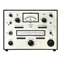
A typical
23
% bandwidth frequency response, weighted by the Hand-Arm filter
of
the 2512, of
the vibration
of
an
electric drill is shown in Fig.4.14.
000000000
OOOOOOOOOOOOOOOOOOOOOOOOOODDDDDODDOOODOD
Brtiel &
Kjaer
Potentiometer
Range:
~dB
Rectifie
r:_Lower
Lim. Freq
.:
_Hz
Wr
. Speed
:_
mm
/sec. Paper
Speed
:
_mm
/sec.
50
25
o
75
. .• . . .
1
Measuring Obj.dB dB
Hand
-
Arm40
20
Rec
. No 10
23
%
Analy~~o
15
using 1621
withH~
Arm
Filter
20 10
Rec
.
No
.:
_10
5
Date:
__
Sign:
__
0
0
1
ms
2--1--~
--~-
-
-
,oo
~
10
20
Hz
OP
0124
Multiply
Freq.
Scale
by
__
0_
, 1
__
-
~
-
-
500
1000
2000 Hz 5000 10000 20000 40000 D A
B
C Lin.
Zero Level:
__
_
(1612/2112) A B C
Lin810460
Fig.
4.
14.
Typical frequency analysis recorded using the system
of
Fig.4.12.

 Loading...