Do you have a question about the Bruker BLAH1000 E and is the answer not in the manual?
Provides an overview of the BLAH1000 E Amplifier, its applications, and key features.
Explains the labels on the unit, including the identifying plate and manufacturer's name plate.
Describes various warning signs and symbols used in the manual and on the equipment for safe operation.
Details the initial checks upon receiving the equipment, including damage assessment.
Outlines environmental conditions and general requirements for installing the equipment.
Specifies the power supply requirements for the BLAH1000 E Amplifier.
Lists critical checks to be performed before applying power for the first time.
Provides step-by-step instructions for powering on the amplifier correctly.
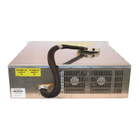
Describes front panel components, indicators, and connectors.
Details the types and functions of coaxial connectors on the front panel.
Describes the Ethernet connector and its pin assignment for network communication.
Visual guide showing the amplifier's front panel layout.
Details the rear panel connections, including the power supply connector.
Visual guide showing the amplifier's rear panel layout.
Describes the external power supply unit required for the amplifier.
Details the indicators on the external power supply's front panel.
Details and shows the rear panel of the external power supply.
Provides a general overview of the BLAH1000 E amplifier system architecture.
Explains the fundamental principles and operational logic of the amplifier.
Details RF path elements including relays, splitter, amplifier, and combiner.
Explains the functions and role of the BLA Control Board in managing the amplifier.
Details the amplifier's protection mechanisms and monitored parameters.
Describes the BLA Extension, Status LED, and BIS boards.
Details the function of the Supply Status Board for monitoring power supplies.
Explains how to access the amplifier's control interface via its IP address.
Describes the information available in the sub toolbar and the default device information screen.
Details how to view the current operational status of the amplifier.
Introduces the advanced operations section of the user interface.
Explains how to view and change the amplifier's operational limits.
Provides instructions on how to modify the amplifier's operating limits.
Describes how to view and configure the RF path routing for the amplifier inputs.
Introduces the maintenance functions available in the sub toolbar.
Explains how to perform self-tests and software resets for troubleshooting.
Details the procedure for updating the amplifier's firmware.
Shows information about the current BIS programmed on the amplifier.
Lists common characteristics of the amplifier, including protection and connectors.
Provides detailed specifications for the High Resolution 100W output channel.
Provides detailed specifications for the Solid 1000W output channel.
Details preventive maintenance procedures for the amplifier's RF module fans.