18 (53) BRUKER BIOSPIN Operating & Service Manual Version 002
Operation
External Power Supply 4.3
The external power supply has the Bruker Part Number P/N:W1304007.
This part number has been established for identification of use by internal jumper
settings.
It provides a first output voltage channel of +32Vdc, 50A maximum with a current
peak of 175A maximum for 100ms pulse width and 5% duty cycle and also a
second output voltage channel of +32Vdc, 18A maximum with a current peak of
45A maximum for 100ms pulse width and 10% duty cycle.
This unit provides also auxiliaries supplies of +15Vdc; 2A, -15Vdc; 0.5A and
+3.3Vdc; 4A.
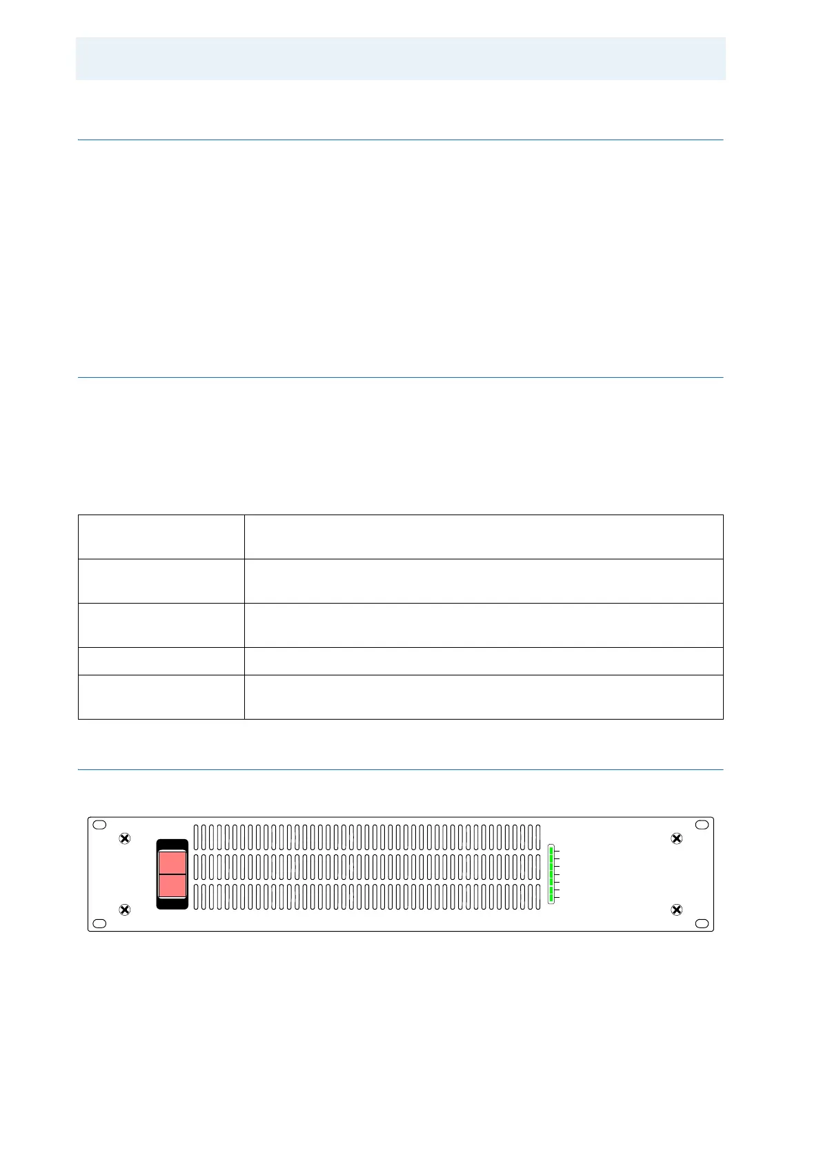
Front Panel & Indicators Description 4.3.1
The external Power Supply front panel is provided with 5 indicators for status
monitoring.
Normal operation is indicated when following LED's are ON.
Table 4.5. Power Supply Indicators Assignment
Device Front View 4.3.2
Figure 4.6. Power Supply Front Panel Design
+28/30/32V A ON 175A Indicates that the +32V first voltage output channel supply is active.
Internal setting.
+28/30/32V B ON 45A Indicates that the +32V second voltage output channel supply is active.
Internal setting.
+12/+15V ON Indicates that the +15V supply is active.
Internal setting.
-15V ON Indicates that the -15V supply is active.
+3,3V/+5V ON Indicates that the +3,3V supply is active.
Internal setting.
+28/30/32V A ON 175A
+12V/+15V ON
-15V
+3.3V/+5V
+28/30/32V B ON 45A
B-PSU 28-30-32V
1
O
ON
ON
(200mA/100ms)