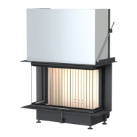
Put the ‘front inner ring’ in place The inner ring embraces the in-
ner shell parts and holds these
parts in position. Make sure that
the width of joints is small as pos-
sible.
Put the ‘external shell, left side’ in
place
The external shell is attached at
the bottom on the base ring.
Illustration 18: Front inner ring and ex-
ternal shell, left side in place
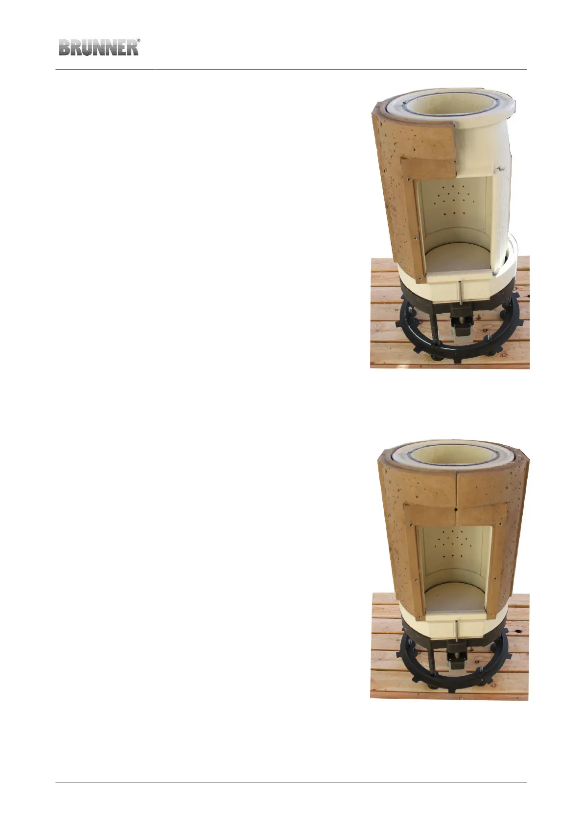
Completion of combustion chamber external shell
Working step Note
Put the ‘external shell, right side’
in place
The even surface of the external
shell parts together with the base
ring edge provides the attachment
surface for the stove front. Align
the parts to receive a flat surface,
make sure that the width of joints
is small as possible.
Illustration 19: External shell parts as-
sembled and aligned
© 2021 Brunner GmbH Installation Guide KSO 33 (1.12) 25
 Loading...