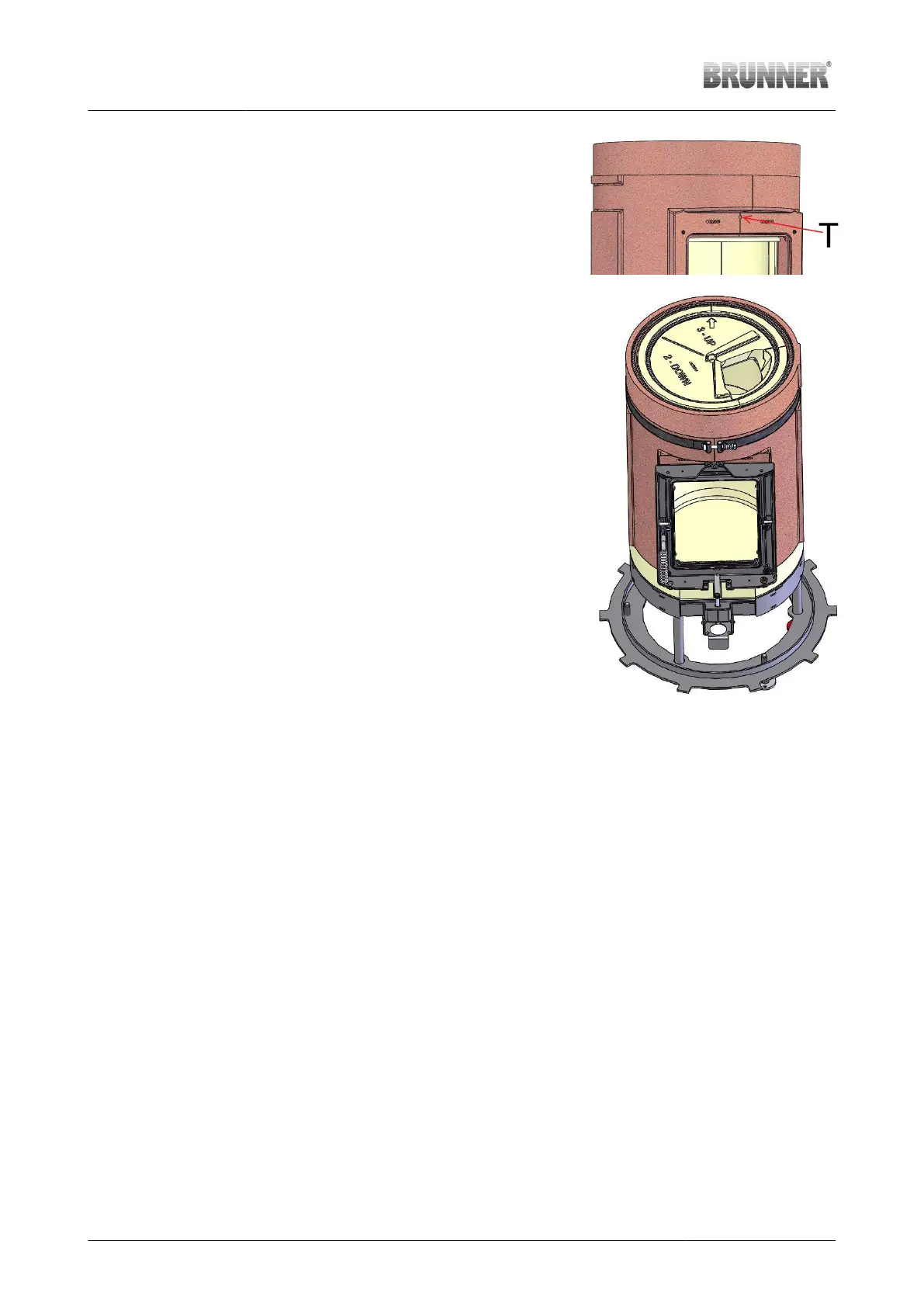
1. Only for stoves with manual op-
eration
For stoves with manual operation,
the hole (T) for thermocouple in-
stallation above the stove door
must be sealed with the attached
sealent.
2. Check the mounting surface for
combustion chamber
The mounting surface must be
plane and even - align the parts
when necessary. Remove the
screws from the combustion
chamber external shell. These
screws will be not needed any
more.
3. Prepare screws In the attached screw kit, there
are 6 pieces of M8x35 screws.
For assembly, use a torque
wrench with a SW5 Allen key
4. Attach the front At the front there is a 14mm hole
on the lower transverse web - the
air adjuster of the main unit must
protrude through this hole. After
attaching the front to the mounting
face, the air adjuster must be free
and easy to move. The position of
combustion chamber on the main
unit can be still changed.
5. Affix the front with screws Mount the screws and tighten
crosswise. Allowable torque:
6Nm.
Illustration 24: Combustion chamber
with installed front
28 Installation Guide KSO 33 (1.12) © 2021 Brunner GmbH