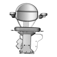
©2011,2005 BRUNO INDEPENDENT LIVING AIDS, INC.®
SRE-2750 INSTALL 05-17-2011
18
4. Fold down the footrest.
5. LOOSEN BUT DO NOT REMOVE* the (3) M10 gold zinc
hex head cap screws (17 mm wrench). See left.
6. Place a level on the footrest.
7. Pivot the seat post right or left as necessary to level
the footrest.
8. While holding the seat post steady, tighten the (3) M10
gold/zinc screws to a torque of 80 ft. lbs.
Right-hand installations
1. Fold down the footrest.
2. Remove the M8 hex head screw (see left). This is the
safety lock screw
3. LOOSEN BUT DO NOT REMOVE* the (3) M10 gold zinc
hex head cap screws (17 mm wrench). See above left.
4. Pivot the seat post assembly to the opposite side of the
carriage.
5. Re-insert and tighten the M8 zinc hex head cap (safety
lock) screw.
6. Place a level on the footrest.
7. Pivot the seat post right or left as necessary to level
the footrest.
8. While holding the seat post steady, tighten the (3) M10
gold/zinc screws to a torque of 80 ft. lbs.
The screw will penetrate a hole in the angle retainer lock
plate mounted behind the carriage wall.
*If screws are accidentally
removed, be sure to
re-install the safety
lockwashers (installed at the
factory) when you
re-install the screws.
X
X
X
(3) M10 gold zinc hex head cap screws
M8 zinc hex head cap screw
Refer to torque specications on page 5.
INSTALLATION



 To Next Page