©2011,2005 BRUNO INDEPENDENT LIVING AIDS, INC.®
SRE-2750 INSTALL 05-17-2011
20
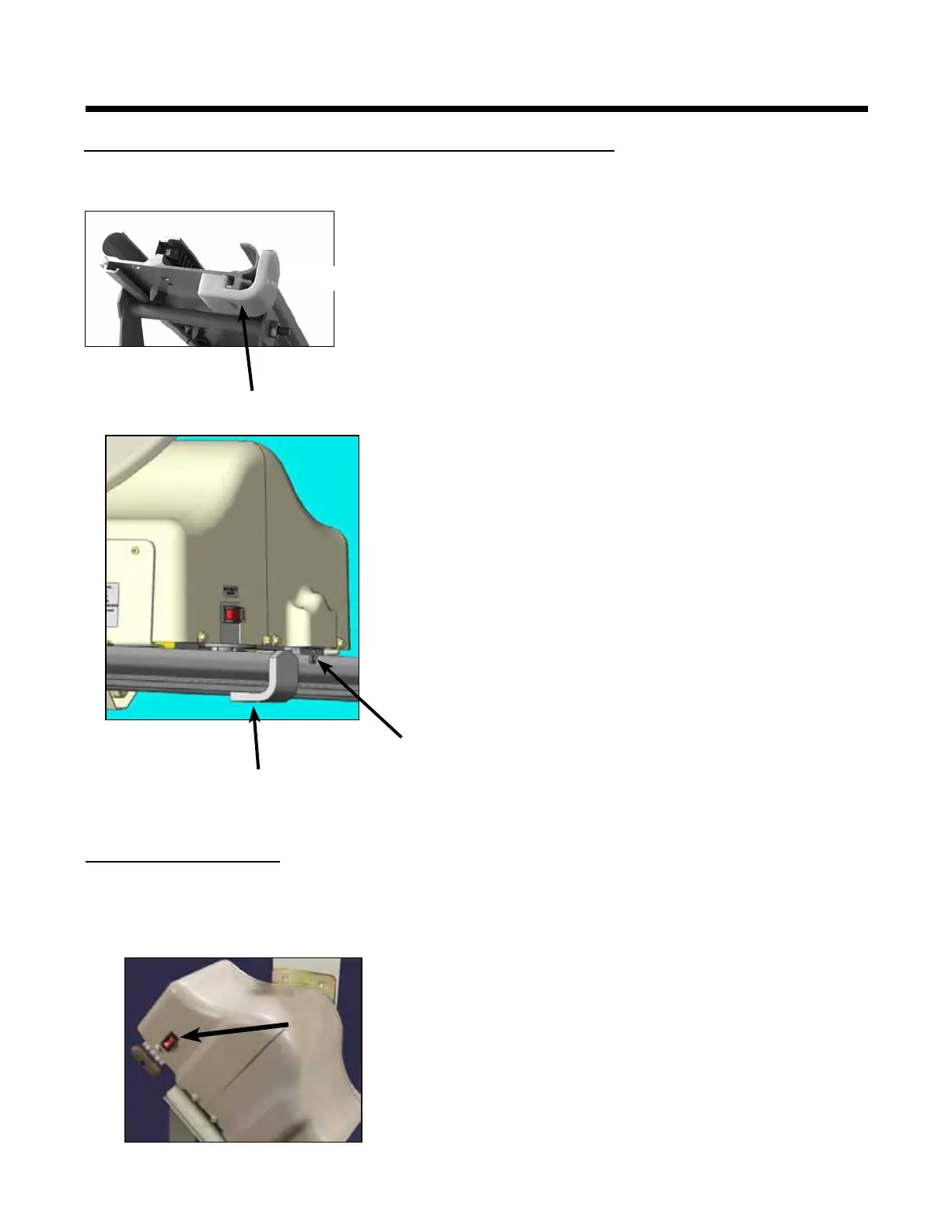
INSTALLING THE FINAL LIMIT RAMP AND SWITCH
1. Run the carriage to the top of the rail.
2. Note where the nal limit switch is located in
relation to the upper leg.
3. If the nal limit switch is below the upper leg,
snap the plastic nal limit ramp onto the rail just
below the upper leg.
4. Make sure the carriage is at the top of the rail,
then proceed to Step No. 5.
5. If the nal limit switch is above the upper leg, run
the carriage down the rail (approx. 10 cm) to
create room to remove the upper end cap.
6. Slide the nal limit ramp onto the upper end of
the rail.
7. Put the end cap back on.
8. Run the carriage to the top of the rail.
9. Adjust the limit ramp up or down the rail so that
it is located just before the point where the small
roller of the nal limit switch touches the ramp.
10. Tighten the (2) M5 screws (Allen wrench) to
secure the nal limit ramp.
The on/off switch is built into the circuit breaker to
protect the battery, controller and motor circuits in the
Elevator carriage.
It is unlikely that this circuit breaker will ever “trip”
during normal use. However, if the Elevator should
fail to operate, check the circuit breaker as a rst
troubleshooting stop and reset it if necessary.
If the circuit breaker should trip, determine the cause
and correct the situation.
The most frequent causes of a tripped circuit breaker
are (1) a foreign object jamming the rail or gear rack,
and (2) exceeding the maximum rated load capacity.
nal limit ramp
(2) M5 screws
roller
nal limit ramp
CIRCUIT BREAKER
INSTALLATION


 To Next Page