WARNING: Never purge a line into a combustion
chamber. Never use matches, candles, flame, or other
sources of ignition for the purpose of checking leakage.
Use a soap-and-water solution to check for leakage. A
failure to follow this warning can cause a fire, explosion,
personal injury, or death.
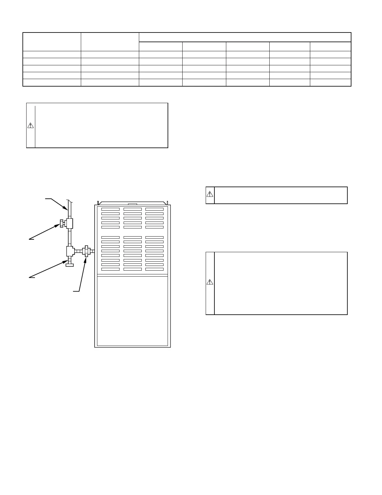
Install a sediment trap in the riser leading to the furnace. The trap
can be installed by connecting a tee to the riser leading from the
furnace. Connect a capped nipple into the lower end of the tee. The
capped nipple should extend below the level of the gas controls.
(See Fig. 14.)
Apply joint compound (pipe dope) sparingly and only to the male
threads of each joint. The compound must be resistant to the action
of propane gas.
Install an accessible manual shutoff valve upstream of the furnace
gas controls and within 72 in. of the furnace. A 1/8-in. NPT
plugged tapping is provided on the gas valve for test gage
connection. Installation of an additional 1/8-in. NPT plugged
tapping, accessible for test gage connection, installed immediately
upstream of the gas supply connection to the furnace and down-
stream of the manual shutoff valve, is not required. Place ground
joint union between the gas control manifold and the manual
shutoff valve.
Piping should be pressure tested in accordance with local and
national plumbing and gas codes BEFORE furnace has been
attached. If test pressure exceeds 0.5 psig (14-in. wc), gas supply
pipe must be disconnected from furnace and capped before
pressure test. If test pressure is equal to or less than 0.5 psig (14-in.
wc), turn OFF electric shutoff switch on gas valve before test. It is
recommended that ground joint union be loosened before pressure
testing. After all connections have been made, purge lines and
check for leakage with regulated gas supply pressure.
VI. ELECTRICAL CONNECTIONS
A. 115-v Wiring
Refer to the unit rating plate or Table 5 for equipment electrical
requirements. The control system requires an earth ground for
proper operation.
CAUTION: Do not connect aluminum wire between
disconnect switch and furnace. Use only copper wire.
Make all electrical connections in accordance with the National
Electrical Code (NEC) ANSI/NFPA 70-1999 and local codes or
ordinances that apply. For Canadian installations, all electrical
connections must be made in accordance with CSA C22.1 Cana-
dian Electrical Code, or authorities having jurisdiction.
WARNING: The cabinet MUST have an uninterrupted
or unbroken ground according to NEC ANSI/NFPA
70-1999 and Canadian Electrical Code, CSA C22.1 or
local codes to minimize personal injury if an electrical
fault should occur. This may consist of electrical wire or
conduit approved for electrical ground when installed in
accordance with existing electrical codes. Do not use gas
piping as an electrical ground. Failure to follow this
warning could result in electrical shock, fire, or death.
The junction box can be moved to left-hand side of furnace when
a left-hand side power supply is desired. Remove 2 screws holding
the junction box. Mount junction box on left-hand side of furnace.
Holes have been provided in casing. When moved, tuck wiring
harness behind clip provided to keep extra wire lengths out of the
way.
NOTE: Proper polarity must be maintained for 115-v wiring. If
polarity is incorrect, the furnace control status LED will flash
rapidly and prevent heating operation.
B. 24-v Wiring
Refer to ESD Precautions Procedure before proceeding with 24-v
connections.
Make field 24-v connections at 24-v terminal block. (See Fig. 15.)
Connect terminal Y/Y2 as shown in Fig. 16 or 17 for proper
cooling operation. Use only AWG No. 18 or larger, color-coded
copper thermostat wire.
The 24-v circuit contains an automotive-type, 3-amp fuse located
on main control. Any 24-v electrical shorts during installation,
service, or maintenance could cause this fuse to blow. If fuse
replacement is required, use ONLY a 3-amp fuse. The control will
flash code 24 when fuse needs replacement.
TABLE 4—MAXIMUM CAPACITY OF GAS PIPE*
NOMINAL
IRON PIPE
SIZE (IN.)
INTERNAL
DIAMETER
(IN.)
LENGTH OF PIPE (FT)
10 20 30 40 50
1/2 0.622 175 120 97 82 73
3/4 0.824 360 250 200 170 151
1 1.049 68 465 375 320 285
1-1/4 1.380 1400 950 770 660 580
1-1/2 1.610 2100 1460 1180 990 900
* Cubic ft of gas per hr for gas pressures of 0.5 psig (14-in. wc) or less, and a supply line pressure drop of 0.5-in. wc (based on a 0.60 specific gravity gas). Ref: Table 9-2,
NFGC.
Fig. 14—Typical Gas Pipe Arrangement
A89417
GAS
SUPPLY
MANUAL
SHUTOFF
VALVE
(REQUIRED)
SEDIMENT
TRAP
UNION
—10—