II. SEQUENCE OF OPERATION
Using schematic diagram in Fig. 19, follow the sequence of
operation through the different modes. Read and follow diagram
very carefully.
NOTE: The GE ICM2+ BLWM speeds are infinitely variable
from 300 to 1400 rpm and are dynamically controlled to precisely
control airflow rate (CFM). The ICM2+ motor ramps to speed at
a controlled rate to reduce start-up noise perception (4 to 11 sec,
depending on the target CFM). The ICM2+ motor ramps down
slowly to a stop in the same time as ramp-up time. ICM2+ ramp-up
and ramp-down times are additive to blower-on and -off delays,
respectively. The ICM2+ is 115-v energized whenever power is
available at furnace control, but operates only when 24-v motor
control input(s) are on.
NOTE: If a power interruption occurs during a call for heat
(W/W1 or W/W1 and W2) and if the thermostat is still calling for
gas heating, the control will start a 90-sec blower only on period
2 sec after power is restored. The red LED will flash code 12
during the 90-sec period, after which the LED will be on
continuously as long as no faults are detected. The ICM2+ motor
will operate at low-gas heat CFM after a power interruption in
either low- or high-heat. After 90-sec period, furnace will respond
to the thermostat normally.
The blower door must be installed for power to be conducted
through blower door interlock switch (ILK) to furnace control
(CPU), transformer (TRAN), inducer motor (IDM), blower motor
(BLWM), hot surface ignitor (HSI), and gas valve (GV).
1. Adaptive Heating Mode—Single-Stage Thermostat with
2-Stage Heating (See Fig. 16 for thermostat connections.)
NOTE: In response to thermostat call for heat R to W/W1, control
selects high-heat heating only with HIGH HEAT ONLY switch
(SW1) set to ON regardless of LOW HEAT switch (SW2) setting.
With HIGH HEAT ONLY switch set to OFF, LOW HEAT switch
selects either low-heat heating only mode when set to ON, or the
adaptive heating mode when set to OFF in response to a thermostat
call for heat R to W/W1. (See Tables 6 and 7, and Fig. 18 for
description of switch settings or Fig. 19 for control circuit
diagram.)
This furnace can operate as a 2-stage furnace with a single-stage
thermostat because furnace control CPU includes a programmed
adaptive sequence of controlled operation, which selects low- or
high-gas heat operation. This selection is based upon the stored
history of the lengths of previous gas heating on/off periods of the
single-stage thermostat.
The furnace will start up in either low- or high-gas heat. If the
furnace starts up in low-heat, the control CPU determines low-heat
on time (from 0 to 16 minutes) which is permitted before switching
to high-heat.
If power is interrupted, the stored history is erased. When this
happens, the control CPU selects low-heat for 16 minutes and then
switches to high-heat, as long as the thermostat continues to call
for heat. Subsequent selection is based on stored history of
thermostat cycle times.
When thermostat calls for heat, R-W/W1 circuit closes. The
furnace control performs a self-check, verifies that the pressure
switch contacts for low- and high-heat (LPS and HPS) are open,
and starts motor IDM in low speed or high speed as appropriate.
a. Inducer prepurge period—A 15 sec prepurge period
begins when LPS contacts close. For high-heat opera-
tion, both LPS and HPS must be closed. For low-heat
operation, only LPS must be closed.
b. Igniter warm-up—At end of the prepurge period, the
HSI is energized for a 17-sec igniter warm-up period.
c. Trial-for-ignition sequence—When igniter warm-up pe-
riod is completed, the main gas valve relay contacts
(MGVR-1 and -2) (and high-heat pressure switch relay
HPSR for high-heat operation) close to energize low-
and high-heat gas valve solenoid(s) (GV) and humidifier
TABLE 6—SETUP SWITCH DESCRIPTION
SETUP
SWITCH NO.
NORMAL
POSITION
DESCRIPTION
OF USE
SW-1
Only High-Gas Heat
OFF (Staged Gas Heat)
Turn switch on to obtain only high-gas-heat operation on
any call for heat regardless of whether R-W/W1, or
R-W/W1, -W2 is closed. SW-1 overrides SW-2.
SW-2
Low-Gas Heat (Adaptive Mode)
OFF (Single-Stage Thermostat)
Turn switch off for installations with single-stage thermo-
stats; control selects low-gas-heat or high-gas-heat opera-
tion based on previous cycles. Turn switch on for installa-
tions with 2-stage thermostats to permit only low-gas-heat
operation in response to closing R-W/W1. High-gas heat is
supplied only when R to W/W1 and W2 are closed.
SW-3 and SW4 OFF, ON
Switches control gas heating mode blower-off delay. (See
Table 7.)
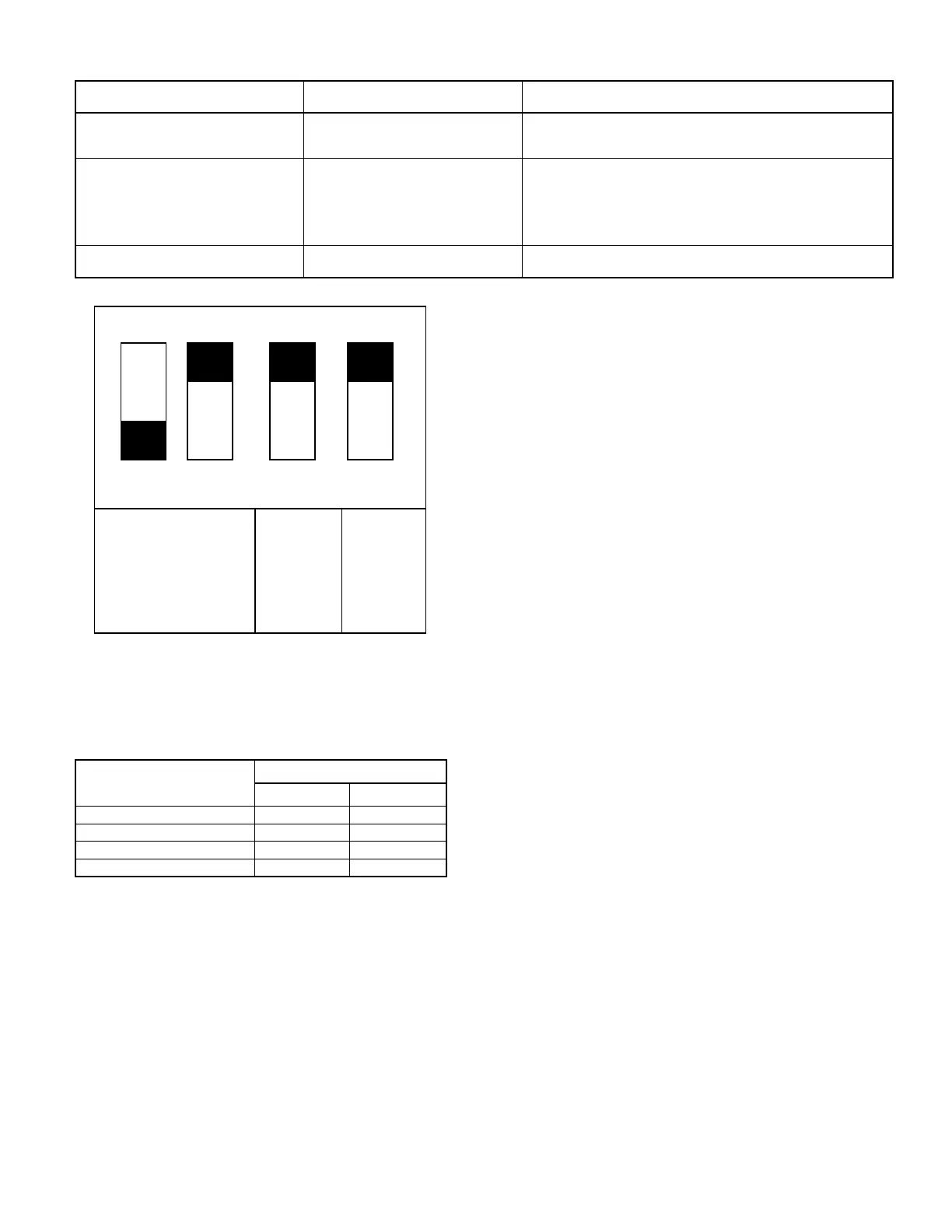
Fig. 18—Setup Switches on Furnace Control
(Factory Settings)
A96402
BLOWER-
OFF
DELAY
LOW
HEAT
(ADAPTIVE
ALGORITHM)
HIGH
HEAT
ONLY
43 2
OFF
ON
1
TABLE 7—BLOWER-OFF DELAY SETUP
SWITCH (SW) POSITION
DESIRED HEATING
MODE BLOWER-OFF
DELAY (SEC)
SETUP SWITCH
SW-3 SW-4
90 OFF OFF
135 OFF ON
180 ON OFF
225 ON ON
—13—