b. The hot surface igniter is energized for 15 sec, then
de-energized.
c. The blower motor operates at continuous-fan airflow for
7 sec then stops.
d. The blower motor operates at high-gas heat airflow for 7
sec. The gas valve and humidifier terminal HUM are not
energized for safety reasons.
e. The blower motor operates at single-speed cooling/heat
pump heating airflow (or 2-speed heat pump high-
heat/high-cooling) for 7 sec, then stops.
NOTE: The EAC terminals are energized when the blower is
energized.
2. After all connections have been made, purge gas lines and
check for leaks.
WARNING: Never purge a gas line into a combustion
chamber. Never use matches, candles, flame, or other
sources of ignition for the purpose of checking leakage.
Use a soap-and-water solution to check for leakage. A
failure to follow this warning can cause a fire, explosion,
personal injury, or death.
3. To operate furnace, follow procedures on operating instruc-
tions label attached to furnace.
4. With furnace operating, set thermostat below room tem-
perature and observe that furnace goes off. Set thermostat
above room temperature and observe that furnace restarts.
V. ADJUSTMENTS
1. Set gas input rate.
The gas input rate must be set for both high- and low-stage heat.
Each adjustment is made independently at the gas control regula-
tors. The gas valve regulator has been nominally set at 1.5-in. wc
for low-stage and 3.5-in. wc for high-stage for natural gas.
Furnace gas input rate on rating plate is for installations at altitudes
up to 2000 ft.
In the U.S.A., input rating for altitudes above 2000 ft must be
reduced by 4 percent for each 1000 ft above sea level.
In Canada, input rating must be derated by 10 percent for altitudes
of 2000 ft to 4500 ft above sea level.
Furnace input rate must be within ±2 percent of input on furnace
rating plate.
2. Determine natural gas orifice size and manifold pressure for
correct input.
a. Obtain yearly gas heat value average (at installed alti-
tude) from local gas supplier.
b. Obtain yearly gas specific gravity average from local gas
supplier.
c. Verify furnace model. Table 11 can only be used for
model 333BAV/333JAV Furnaces.
d. Find installation altitude in Table 11.
NOTE: For Canada altitudes of 2000 to 4500 ft, use U.S.A.
altitudes of 2001 to 3000 ft in Table 11.
e. Find closest natural gas heat value and specific gravity in
Table 11.
f. Follow heat value and specific gravity lines to point of
intersection to find orifice size and low- and high-heat
manifold pressure settings for proper operation.
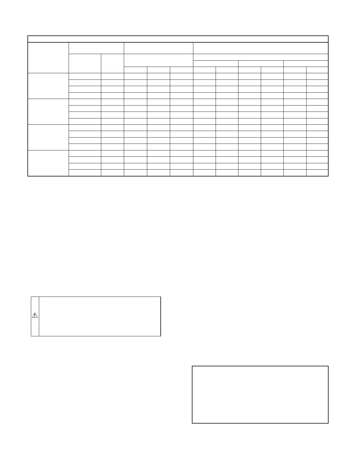
TABLE 10—HEAT PUMP COMFORT HEATING NOMINAL CFM
AT UP TO 0.70-IN. W.C. ESP (WITH FILTER)
AC/HP JUMPER POSITION: HP—CMFT, HEAT PUMP—COMFORT, HEATING AIRFLOW
Furnace Size
Airflow
Selection
Single-Speed
CFM
Two-Speed (High/Low)
CFM
Cool Size
Jumper
Position
Tons
Cool CFM Per Ton
Jumper Position
Cool CFM Per Ton Jumper Position
400 350 315
400 350 315 High Low High Low High Low
060
LO 1-1/2 540 500* 500* 565 500* 500* 500* 500* 500*
M-LO 2 720 630 570 780 500* 660 500* 595 500*
M-HI 2-1/2 900 790 710 945 585 830 515 740 500*
HI 3 1080 945 755 1135 700 990 610 895 555
080
LO 2-1/2 900 785 710 945 605 825 535 1040 500*
M-LO 3 1080 945 850 1135 715 990 630 1190 560
M-HI 3-1/2 1260 1100 990 1325 830 1150 725 890 655
HI 4 1440 1260 1135 1510 940 1325 825 1040 740
100**
LO 3 1075 940 855 1130 700 980 700 1190 700*
M-LO 3-1/2 1260 1100 990 1325 820 1155 750 1490 700*
M-HI 4 1440 1260 1130 1510 935 1350 825 885 740
HI 5 1900 1575 1420 1890 1170 1655 1035 1035 920
120**
LO 3 1045 945 860 1075 780 975 750 750 750
M-LO 3-1/2 1260 1100 980 1280 875 1140 790 790 760
M-HI 4 1440 1255 1125 1485 965 1320 880 880 835
HI 5 1800 1575 1410 1900 1170 1650 1025 1025 970
* Minimum airflow is set for electronic air cleaner: 060—500 CFM, 080—500 CFM, 100—700 CFM, 120—700 CFM
** Air delivery may be reduced by as much as 3 percent when using a single side return.
NOTE:
Continuous-fan settings are 50 percent, 65 percent, or 100 percent of selected cooling airflow.
EXAMPLE: (0—2000 ft altitude)
Heating value = 1075 Btu/cu ft
Specific gravity = 0.62
Therefore: Orifice No. 45
Manifold pressure: 3.4-in. wc for high heat
1.4-in. wc for low heat
*Furnace is shipped with No. 45 orifices.
In this example, all main burner orifices are the correct size and
do not need to be changed to obtain proper input rate.
—19—