E. Filter Arrangement
WARNING: Never operate unit without a filter or with
filter access door removed. A failure to follow this
warning could result in fire, personal injury, or death.
The air filter arrangement will vary due to application and filter
type. The filter may be installed in an external Filter/Media cabinet
(if provided) or the furnace blower compartment. Factory supplied
washable filters are shipped in the blower compartment.
If a factory-supplied external Filter/Media cabinet is provided,
instructions for its application, assembly, and installation are
packaged with the cabinet. The Filter/Media cabinet can be used
with the factory- supplied washable filter or a factory-specified
high-efficiency disposable filter (see cabinet instructions).
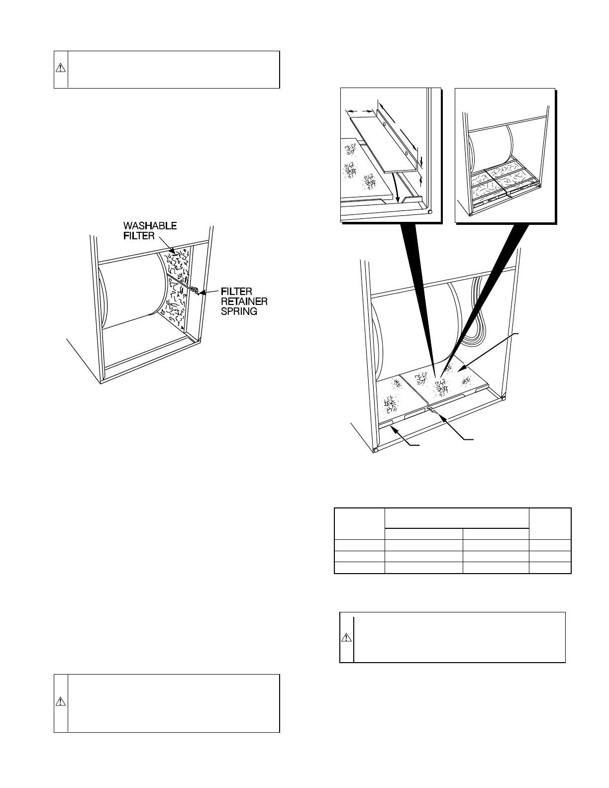
If installing the filter in the furnace blower compartment, deter-
mine location for the filter and move filter retaining hardware, if
necessary, before attaching the return-air duct. After the return-air
duct has been connected to the furnace, install the filter(s) inside
the furnace blower compartment. See Fig. 8 for side return
application and Fig. 9 for bottom return application.
A bottom closure panel is factory installed in bottom of furnace.
When bottom return inlet is desired, remove and discard enclosure
panel.
Filter retaining brackets, supports, and retainers are factory as-
sembled and shipped installed for side return application, with 1
set of all required hardware on each furnace. (See Fig. 8.)
For bottom return applications, remove front and back brackets
and supports from each side. The back bracket(s) are installed in
the rear of the furnace casing. Dimples are provided to mark
mounting screw locations.
Rotate filter side supports 180° so filter will rest on support and
reinstall. Install small U-shaped end of filter retaining rod in rear
bracket. Install front of filter retainer rod as shown in Fig. 9. Two
sets of hardware are needed for furnaces in 24-1/2 in. casings using
2 filters for bottom return. All hardware is provided for filter
installation.
WARNING: Do not install furnace on its back. Safety
control operation will be adversely affected. Never con-
nect return-air ducts to back of furnace. Failure to follow
this warning could result in fire, personal injury, or death.
(See Fig. 4.)
CAUTION: Use care when cutting support rods in filters
to protect against flying and sharp rod ends. Wear safety
glasses, gloves, and appropriate protective clothing. Fail-
ure to follow this caution could result in personal injury.
INSTALLATION
I. UPFLOW FURNACE INSTALLATION
NOTE: Door clip on control door may be removed for upflow
installations.
1. Position furnace in desired location.
Fig. 8—Side Filter Arrangement
A00217
Fig. 9—Bottom Filter Arrangement
A00290
WASHABLE
FILTER
FILTER
SUPPORT
FILTER
RETAINER
17
1
⁄2-IN. WIDE
CASINGS ONLY:
INSTALL FIELD-SUPPLIED
FILTER FILLER STRIP
UNDER FILTER.
1″
24
1
/
2
″
3″
21-IN. WIDE
CASINGS ONLY:
SUPPORT RODS (3)
EXTEND 1/4" ON EACH
SIDE OF FILTER AND
REST ON CASING FLANGE
TABLE 3—FILTER INFORMATION (IN.)
FURNACE
CASING
WIDTH (IN.)
AIR FILTER LOCATED IN BLOWER
COMPARTMENT FILTER SIZE (IN.)*
FILTER
TYPE
Side Return Bottom Return
14-3/16 (1)16X25X1† (1) 14 X 25 X 1 Cleanable
21 (1)16X25X1 (1)20X25X1† Cleanable
24-1/2 (1or2)16X25X1 (1)24X25X1† Cleanable
* Filters may be field modified by cutting filter material and support rods (3) in
filters. Alternate sizes and additional filters may be ordered from your dealer.
†Factory provided with the furnace.
—7—