CAUTION: Recheck the temperature rise. It must be
within the limits specified on the unit rating plate.
Recommended operation is at midpoint of rise range or
slightly above.
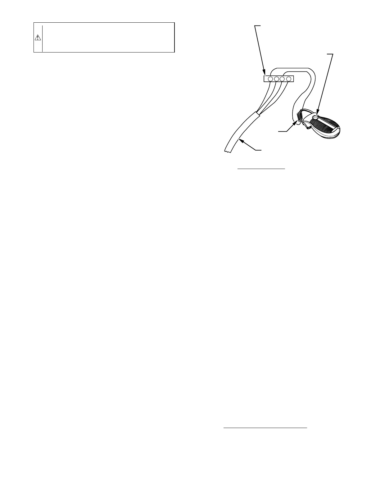
6. Set thermostat heat anticipator.
a. When using a nonelectronic thermostat, the thermostat
heat anticipation must be set to match the amp draw of
the electrical components in the R-W/W1 circuit. Accu-
rate amp draw readings can be obtained at the wires
normally connected to thermostat subbase terminals R
and W/W1. Fig. 24 illustrates an easy method of obtain-
ing actual amp draw. The amp reading should be taken
after blower motor has started and furnace is operating in
low heat. To operate furnace in low heat, first move
SW-2 to ON position, THEN connect ammeter wires as
shown in Fig. 24. The thermostat anticipator should
NOT be in this circuit while measuring current. If
thermostat has no subbase, the thermostat MUST be
disconnected from the R and W/W1 wires during the
current measurement. Return SW-2 to final desired
location after completing the reading. See the thermostat
manufacturer’s instructions for adjusting heat anticipator
and for varying heating cycle length.
b. When using an electronic thermostat, set cycle rate for 3
cycles per hr, if possible.
VI. CHECK SAFETY CONTROLS
The flame sensor, gas valve, and pressure switches were all
checked in the Start-up section as part of normal operation.
1. Check primary limit control.
This control shuts off the combustion control system and energizes
the circulating-air blower motor if the furnace overheats.
The preferred method of checking the limit control is to gradually
block off the return air after the furnace has been operating for a
period of at least 5 minutes. As soon as limit has shut off burners,
the return-air opening should be unblocked. By using this method
to check the limit control, it can be established that the limit is
functioning properly and will operate, if there is a motor failure.
2. Check draft safeguard switch.
The purpose of this control is to cause safe shutdown of the
furnace during certain blocked vent conditions.
a. Disconnect power to furnace and remove vent connector
from furnace flue collar. Be sure to allow time for vent
connector pipe to cool down before removing.
b. Restore power to furnace and set room thermostat above
room temperature.
c. After normal start-up, allow furnace to operate for 2
minutes, then block flue outlet 100 percent. Furnace
should cycle off within 2 minutes.
d. Remove blockage and reconnect vent connector to
furnace flue collar.
e. Wait 5 minutes and then reset draft safeguard switch.
3. Check flow-sensing pressure switches.
This control proves operation of draft-inducer blower.
a. Turn off 115-v power to furnace.
b. Remove gas control door and disconnect inducer motor
leads from wire harness.
c. Turn on 115-v power to furnace.
d. Close thermostat switch as if making normal furnace
start. If hot surface igniter does not glow within several
minutes and control flashes code 32, then flow-sensing
switches are functioning properly. If hot surface igniter
glows when inducer motor is disconnected, shut down
furnace immediately. Determine reason pressure switch
did not function properly and correct condition.
e. Turn off 115-v power to furnace.
f. Reconnect inducer motor wires, replace gas control door,
and turn on 115-v power.
VII. CHECKLIST
1. Put away tools and instruments, and clean up debris.
2. Check SW-1 through SW-4 after completing installation to
ensure desired settings for thermostat type (SW-1 and
SW-2) and blower-off delay (SW-3 and SW-4). Refer to
Tables 6 and 7.
3. Verify manual reset switches have continuity.
4. Ensure blower and gas control access doors are properly
installed.
5. Cycle-test furnace with room thermostat.
6. Check operation of accessories per manufacturer’s instruc-
tions.
7. Review User’s Manual with owner.
8. Leave literature packet near furnace.
Fig. 24—Amp Draw Check With Ammeter
A96316
R Y W G
10 TURNS
THERMOSTAT SUBBASE
TERMINALS WITH
THERMOSTAT REMOVED
(ANITICIPATOR, CLOCK, ETC.,
MUST BE OUT OF CIRCUIT.)
HOOK-AROUND
AMMETER
EXAMPLE:
5.0 AMPS ON AMMETER
10 TURNS AROUND JAWS
=
0.5 AMPS FOR THERMOSTAT
ANTICIPATOR SETTING
FROM UNIT 24-V
CONTROL TERMINALS
—25—